The Taig Lathe
Treadmill Motor Drive and Custom Power Feed
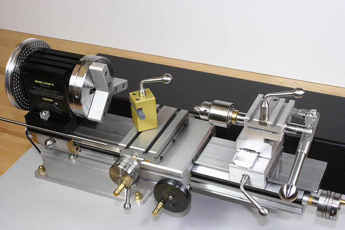
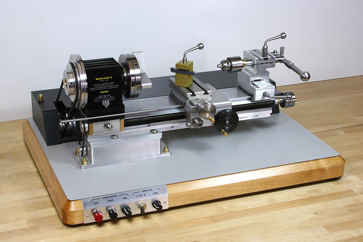
Taig Micro Lathe II With Modifications
This whole tangent – acquisition of a small lathe – started when I had a need to make a tiny 1/8″ diameter internally-threaded sleeve for tensioning a thin aircraft cable. The aircraft cable would have a small brass collar crimped and silver soldered on the end, and the sleeve would rotate freely on the cable as it threaded onto a 4-40 rod, thereby tensioning the cable. The problem wasn’t that I couldn’t chuck the small parts on my Logan/Wards 10″ lathe, but that the lathe couldn’t really achieve the spindle speeds needed to do a good job on the small-diameter parts.
For several months I had been looking for a smaller lathe – something of the Sherline variety – that would be more comfortable to work with at higher spindle speeds. I knew a little about the Taig lathe, but for some fickle reason I didn’t seriously consider it until later in the process. Early on I had also started watching for vintage Unimat lathes on eBay. A Unimat would not be the most practical choice, but I had been fascinated by them since the ’60s when their ads could be seen everywhere in hobbyist magazines and catalogs.
Although I love the old jeweler/watchmaker lathes too – Boley, Levin, Derbyshire, etc., I really wanted something easy to just go out and buy and obtain tooling for, so I limited myself to looking at the following types:
Unimat Lathe
These are widely available on eBay, and accessibility to parts would likely not be an issue. They are reportedly a little flexible under load with only two steel rods for a bed. And the universal motors, although probably adequate given the structural limitations of the lathe, are not well suited for torque at low rpm . It would be a great collectible, especially decked out with all of the accessories, but I’m afraid that I would restore it and put it back in its case to display and not use. I still may end up doing that.
Sherline Lathe
I was ready and willing to pop for a Sherline lathe and a selection of chucks and accessories, based on good experiences I had using one in the early ’80s that I had bought for the engineering lab where I worked. The pricing seems a bit high for anodized aluminum accessories, compared to what you can get in cast-iron/steel accessories for larger lathes, but this is an unfair comparison. The Sherline accessories and the lathes themselves are very well made and are ready to do precise work right out of the box. The problem for me, if it is a problem at all, started because it came in two different bed lengths. And the thought process that followed can give some insight into how my decision-making process works.
The 8.5″ model was really all that was needed, because I do have a larger lathe. But after adding up the cost of everything I realized that it would only be a bit more for the 17″ bed Sherline. Why not go for it? Oh wait a minute – the Sherline doesn’t have a rapid carriage feed for moving up and down that 17″ bed – you have to crank the lead screw a couple hundred turns to travel from end to end. So my thinking turned back to the 8.5″ model – it takes up less space and it’s really all I need. But after adding in the cost of all the tooling for the 8.5″ lathe, the jump to the 17″ bed is insignificant, a small percentage of the overall cost. And yet now I’m getting close to a total price that makes me think I should be getting more than a Sherline for the money. Alas, I don’t need something more substantial, so I reboot back to the 8.5″ model. And so on. I got stuck in this recursive loop for a while until I snapped out of it and did some more research on the Taig.
Taig Lathe
It wasn’t until I ran across this site that I looked at the Taig in a different light. At the link you will find the astounding machine work (and the photographic skills to show it off) of John R. Bentley. Although I knew I wasn’t looking at a stock Taig, it helped me see the possibilities. His modifications and accessories had turned it into something that was more of what I wanted, and in the end I based many of my modifications directly on his ideas.
The Taig won out, not simply because of the lower kit and accessory cost, but more importantly because of the way that it is designed to be accessorized. The aluminum extrusions used for the headstock, tailstock, and under the bed may at first give the appearance of a simplistic design, but nearly every square inch of the lathe has dovetails or T-slots that can be used for accessory attach points. This had never been obvious to me until I studied the designs of some other Taig owners, both at the above site and at Nick Carter’s Taig Lathe Pages.
Consider this as well: the kit price for the lathe bed, headstock spindle, and the carriage/crosslide is currently a little under $170. Now that is only the beginning toward building the basic lathe, but with prices like that you can begin to imagine using the assemblies or individual parts for other tooling accessories or dedicated, single-purpose machines. A $70 headstock could be used for a tool post grinder or some other machining accessory mounted on the compound of a larger lathe. A headstock and bed could be mounted vertically and turned into a sensitive drill. I have seen a Taig lathe adapted with a long bed for use in turning pool cues, and two lathes aligned end to end, their spindles driven in sync, for use as a glassblowing lathe. I’m toying with the idea of using a Taig headstock with index wheel as a light-duty index head that doesn’t require removing the vise. Machine an aluminum block to look like a short section of the lathe bed, clamp this in the milling machine vise, and slip on the headstock/index. Alternating between indexing and vise operations would be simple.
Although Taig does not offer the wide range of tooling and accessories that Sherline has, what they do sell is very attractively priced and it looks like you could buy one (or several) of every accessory that they offer for considerably less than the equivalent items from Sherline. There are opinions out there that would seem to indicate that Sherline quality is consistently very high, and this may command a higher price. All I can say for certain at this point is that what I have seen of all the Taig accessories thus far would indicate that they appear well made and are entirely serviceable for their intended purpose.
Portable at Under 50lbs, and Ready to Work
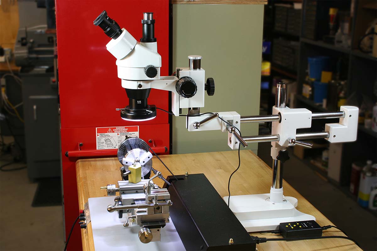
And Low Enough to Slide Under the Microscope
The Basic Kit and Assembly
I won’t spend much any time on the basics of the lathe assembly, since that is well-documented elsewhere. Most of what you see here will be pictures and descriptions of some modifications, and information on some issues and pitfalls that I encountered along the way.
As you may have guessed from the title of this section, I bought the K1019 basic kit rather than the factory assembled version. At the same time I bought a tailstock assembly, a 3-jaw chuck, a steel T-slot faceplate, a tool holder, and an extra spindle to use as a diameter gauge, since I would be machining the pulleys myself. These items were ordered through Nick Carter, and subsequent orders were placed through him as well. He offers an additional 10% discount on most items, and he was very helpful with pre-purchase questions.
The Good…
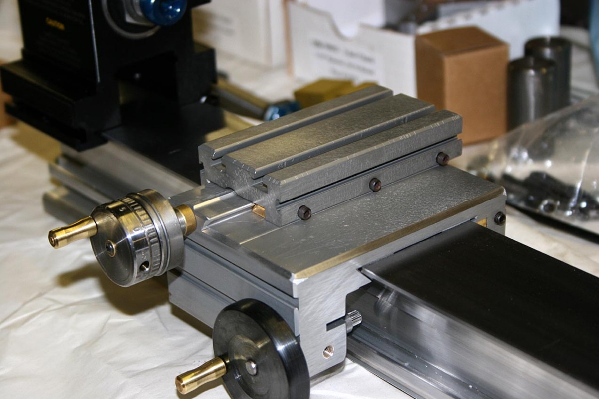
Generally the quality of the items was better than expected, and you can’t help but be impressed at what you get for the price. The lathe bed is quite massive for its size, and from a functional aspect the fit and finish of the key components appeared to be very good. Also, for a manual lathe I personally prefer the Taig’s rack and pinion for carriage motion as opposed to the lead screw that the Sherline uses. If I wanted to equip a lathe for CNC , that might be a different matter, but I have no need for that. Adding a lead screw to the Taig was a bit of work but in the end it has the advantages of both types of drives; the speed of a crank and the precision of a .050″/revolution lead screw.
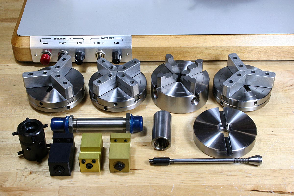
Chucks and Accessories. Good Quality and Inexpensive. Buy Plenty.
The accessories and tooling are much better than I expected, too. Taig sells nice little 3- and 4-jaw self-centering chucks with replaceable aluminum jaw inserts, and a 4-jaw independent chuck with steel jaws. I was a little put off by the bulky look of the replaceable-jaw chucks in the beginning before I realized just how useful machinable jaws can be when you are trying to do precise work. Nice quality internally-threaded steel arbors cost next to nothing-buy a dozen for custom work. A finely finished steel faceplate with T-slots that cost something like $16 is so pretty I hate to clamp anything to it.
The Bad…
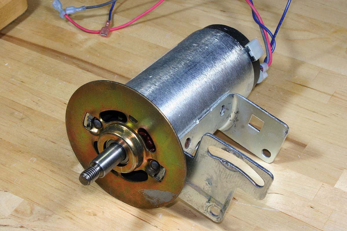
Treadmill Motor Similar to the One Used Here
The Taig doesn’t drop out of the box ready to make chips, at least not quite as easily as a Sherline. You have to mount (or find and mount) a motor, wire it, and generally do a few things that may delay the real projects that you presumably bought a lathe for. Although the recommended fixed-rpm induction motor for the Taig is perhaps not as elegant as the motor/controller combo that Sherline offers, it is relatively inexpensive even if purchased new, and more than likely can be found for next to nothing.
Free treadmills are a good source of motors and controllers, but adapting a motor will generally require the ability to bore a pulley to fit the odd-size shaft. The bottom line is that some time needs to be spent assembling a suitable drive. Depending on how you value your time, the Taig may or may not have any real cost advantage, at least for the basic lathe itself.
Really the only bad thing I have to say about the Taig I saved for the next category:
The Ugly…
Cosmetically, there were some components that were disappointing. Don’t get me wrong-these issues don’t affect the performance, but they do affect the beauty, if that matters to you (and yes, beauty is important). The thing that bothered me the most was the finish work on the carriage extrusion. The extrusion design is really clever, and the critical surfaces were machined and finished very well, but the deburring of all edges prior to anodizing was, to be kind, rough at best.
My carriage as received looked like it had been attacked with an over-zealous angle grinder, with corners ground off and edges ground unevenly. In a way I was expecting this, because I saw evidence of the same thing in John Bentley’s photos, and there is no way that he would miss this sort of detail if there was anything that he could do about it. Oddly enough, this is the type of part that on larger lathes (along with most major components) is usually based on a sand casting with sometimes roughly hand finished edges; that never bothers me. I think it was just that when you see something that looks like it was entirely machined out of bar stock or precise extrusions, hand-ground edges and corners really look out of place.
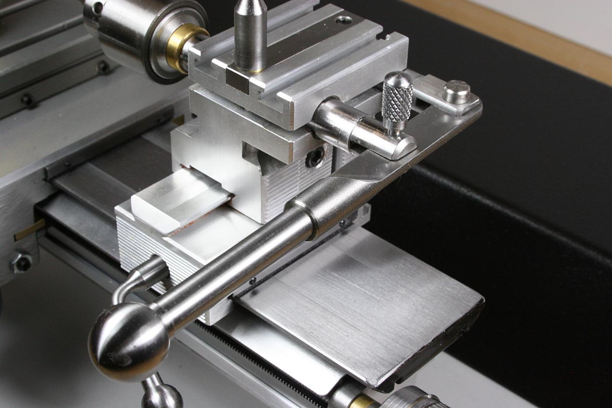
In the end I made a wood mounting fixture for the carriage and mitered the edges the best I could on the milling machine. I couldn’t erase the deepest gouges, but I was a whole lot happier with the result.
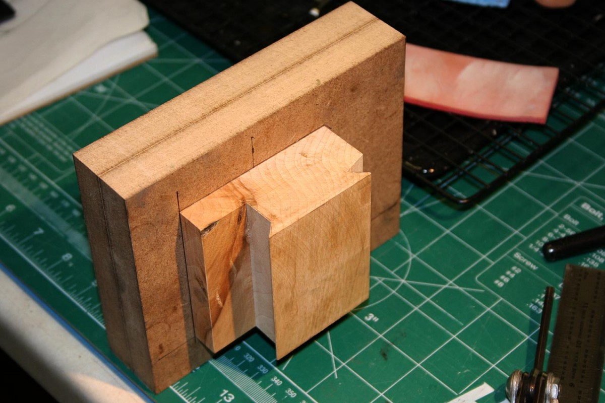
Jig for Clamping Carriage in Milling Machine Vise
Edges of Carriage Cleaned Up a Bit
Vibration, Motor Choices, Mounting, and Belt Tensioning
Minimizing vibration at any spindle speed was of utmost importance, and the motor choice, and how it is mounted, can make a huge difference. For reasons that I question now, I ended up using a 3/16″ wide belt instead of the recommended 1/8″ belt, and this too will affect vibration.
Some, but not all sources of vibration may be obvious:
- Motor vibration – you can’t achieve lower overall lathe vibration than the standalone motor produces. Most induction and treadmill motors have low vibration unless dirty or worn out.
- Pulley balance and concentricity – stock Taig pulleys are very precise, but you need to have a good fit on the motor shaft too. If the motor shaft is a little undersized, the set screws can push the motor pulley a little off-center. And of course if you end up using a treadmill motor you will more than likely need to bore one of the pulleys out to the treadmill shaft size (using the other lathe that you already have, hopefully). This needs to be done very carefully.
- Belt and pulley groove variations – this turned out to be my worst problem, and the reason the recommended 1/8″ belt really may be a better choice than the 3/16″.
In tracking down vibration sources, I started to understand the inherent advantage of using a motor that is small enough to mount directly to the headstock, as Sherline (and John Bentley) does. Belt-to-pulley variations tend to cause the motor to try to pull toward the headstock at cyclic frequencies. For example, imagine that a slightly thicker section of a belt rides in a varying width pulley groove. Compound that with a little less-than-perfect pulley concentricity, and you end up with vibration frequencies that are all over the spectrum. Having the motor and belt tensioner mounted directly on the headstock rigidly spaces the motor and spindle pulleys and makes it easy to force the belt to absorb these vibrations by stretching.
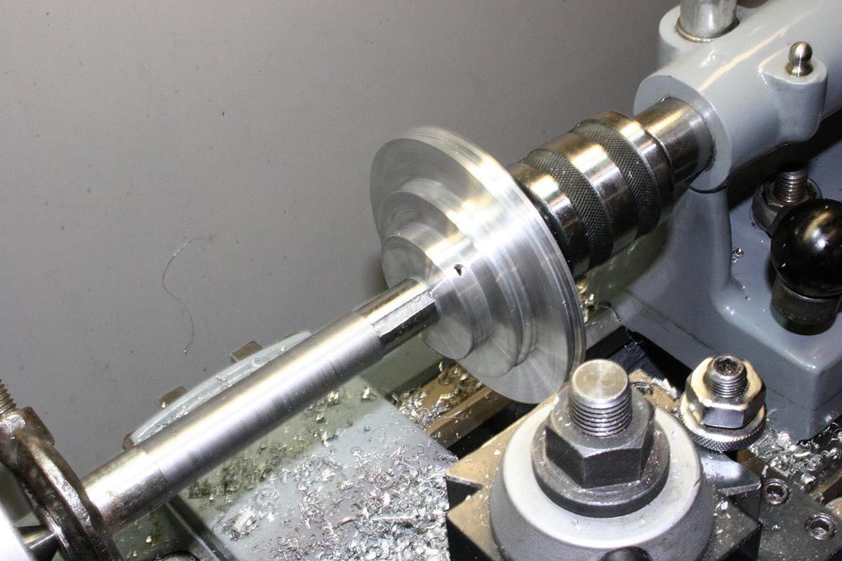
Roughing Out the Headstock Pulley
Unfortunately, mounting the motor and lathe separately on a board creates an easy opportunity for the vibrations induced by the belts and pulleys to get out of hand. Base and motor mount rigidity is important, and be aware that in some circumstances using a resilient mount for the motor may actually aggravate overall vibration. Typical base materials like plywood or particle board should be considered to be flexible from a vibration standpoint. Slabs of aluminum, hardwood, or concrete bases are going to help, but you still need to watch for flexibility at the motor and lathe attach points. Fortunately, a brace can be made that also functions as a belt tensioner and can help approach a more ideal situation.
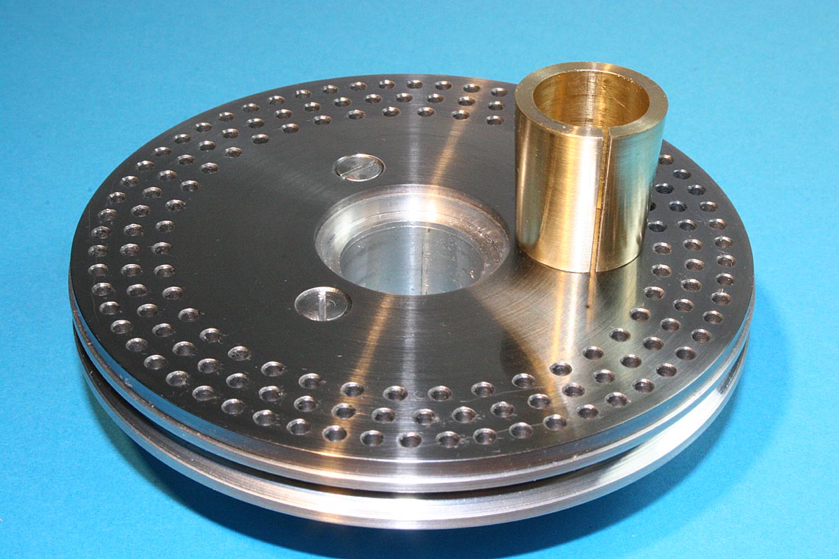
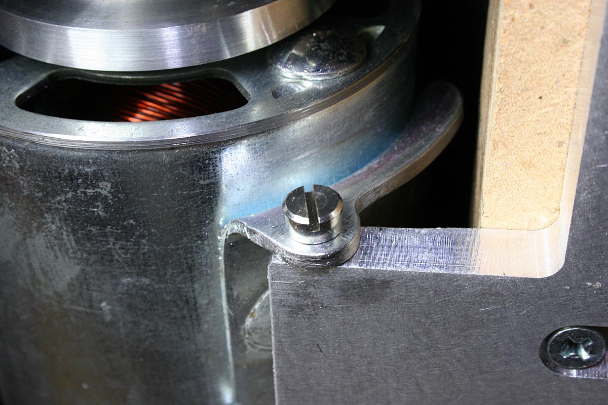
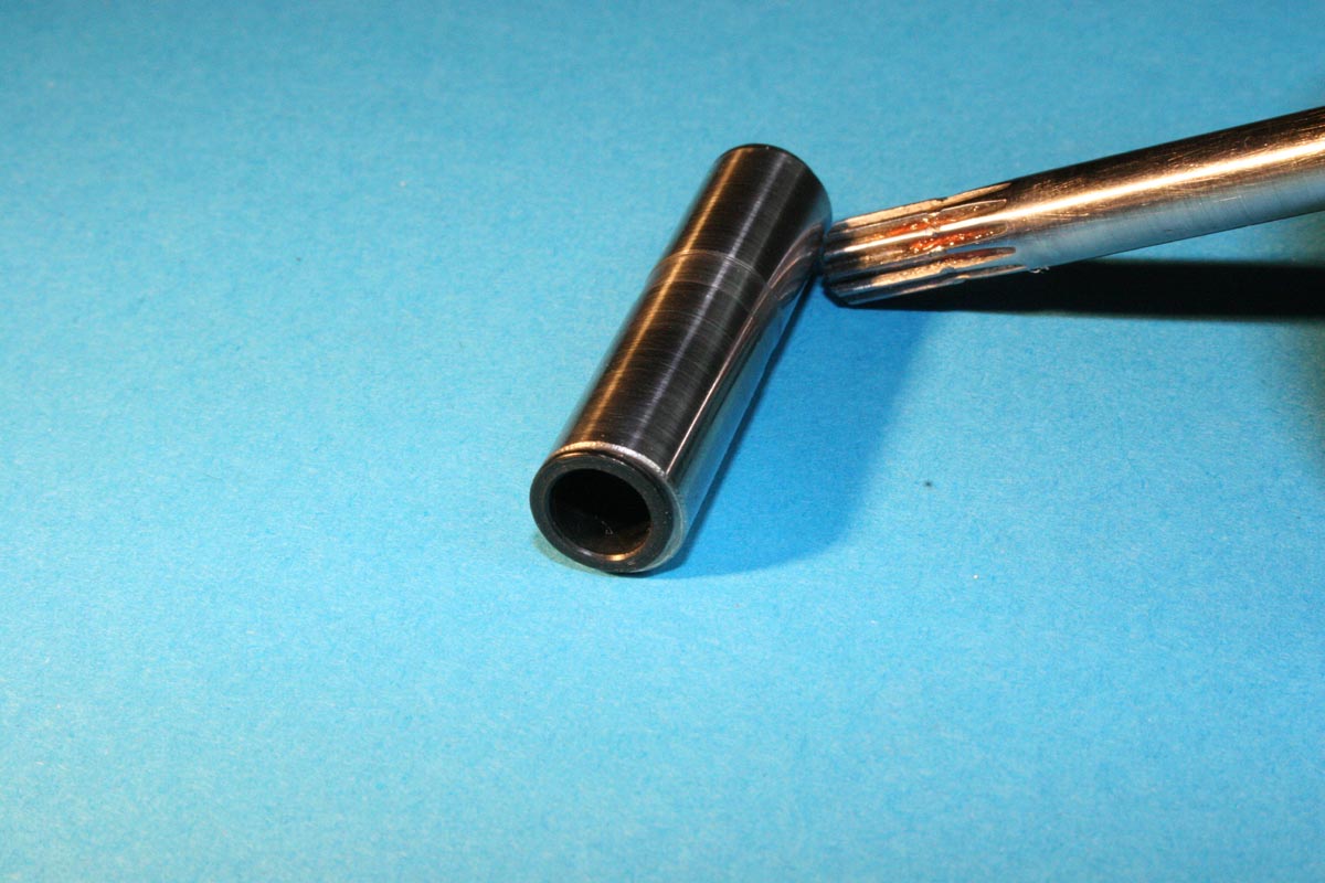
Headstock Pulley with Tapered Bushing
Because of the speed range of the DC motor and the decision to use a 3/16″ belt, I wanted to make custom pulleys for the motor and spindle. And although I was intending to aim for a tight, shrink fit for the spindle pulley bore, it ended up more like a snug fit initially. After a few trial assemblies it became an easy sliding fit – not what I wanted. Tightening the pulley’s set screw introduced a nearly imperceptible wobble, but enough to result in a little vibration at some speeds. Rather than start over and make a new pulley, I thought I would try rebushing it. Somewhere in the process I decided to bore a taper into the pulley and make a split brass bushing with a matching taper on the outside – sort of like a collet.
This turned out to be a worthwhile recovery from a mistake. To mount the pulley, the brass sleeve is slipped onto the spindle and the pulley slipped over the sleeve. A wood clamp is used to compress the pulley onto the spindle and tapered sleeve, and the set screw is tightened securely. This self-centers the pulley every time, and removal is no longer a struggle.
An externally mounted motor drive can be broken down into a model consisting of three legs of a triangle:
- the line from the motor base to the lathe base,
- the line from the lathe base to the center of the spindle, and the
- line from the motor shaft to the lathe spindle.
Geometrically speaking, triangles are rigid structures provided 1) all forces are applied only to the vertices and 2) the length of the triangle’s legs cannot change length (compress or stretch). The first two of these legs in the list above are usually fairly immune to length changes under pure tension or compression. The one that isn’t – the motor shaft to lathe spindle leg – can change length primarily because of flexure of the base board. It is on this leg of the triangle that the pulley/belt variations mentioned above can introduce vibration.
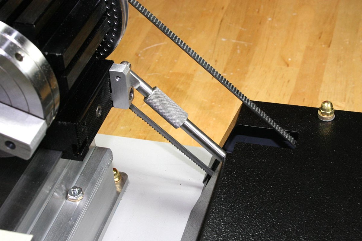
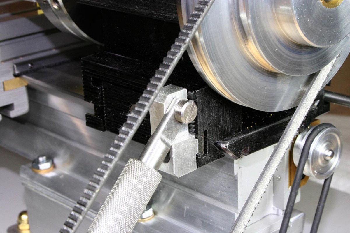
A Nearly Ideal Location For a Belt Tensioner
Fortunately, mounting some sort of rigid member between the motor and the headstock can greatly reduce the pulley/belt induced vibrations. It also serves as a convenient location to put a belt tensioner to keep that 1/8″ belt tightened up to a middle C note, or something like that.
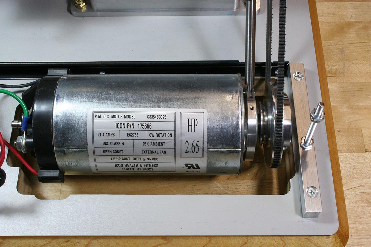
I searched for a long time but could not find an acceptable high voltage DC motor that would fit on the headstock (short of buying a Sherline motor & control, which just seemed wrong at this point). And since I wanted continuous speed control, a treadmill motor seemed to be my only real option. It seemed huge for this size lathe, but with some creative mounting it worked out fine, and torque is NOT a problem.
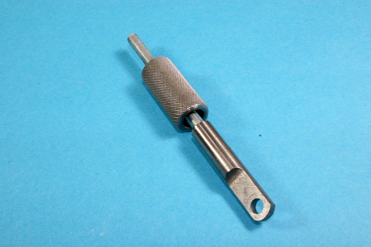
The die-cast end flange of the motor was turned down to match the motor can diameter, and the bulk of the motor mount that is commonly spot-welded to the motor case was cut down to the bare minimum needed to created a pivot mount. To provide attach points for the motor to the base, a 5/16″ thick aluminum plate was mounted in the wood base and to the lathe base itself. An aluminum ring was machined to fit around the motor’s bearing flange to accommodate an attach point for one end of the knurled belt tensioner assembly. Finally, a bracket was machined to fit on a little section of T-slot in the back of the headstock and provide a close, but not perfect attach point for the top end of the tensioner.
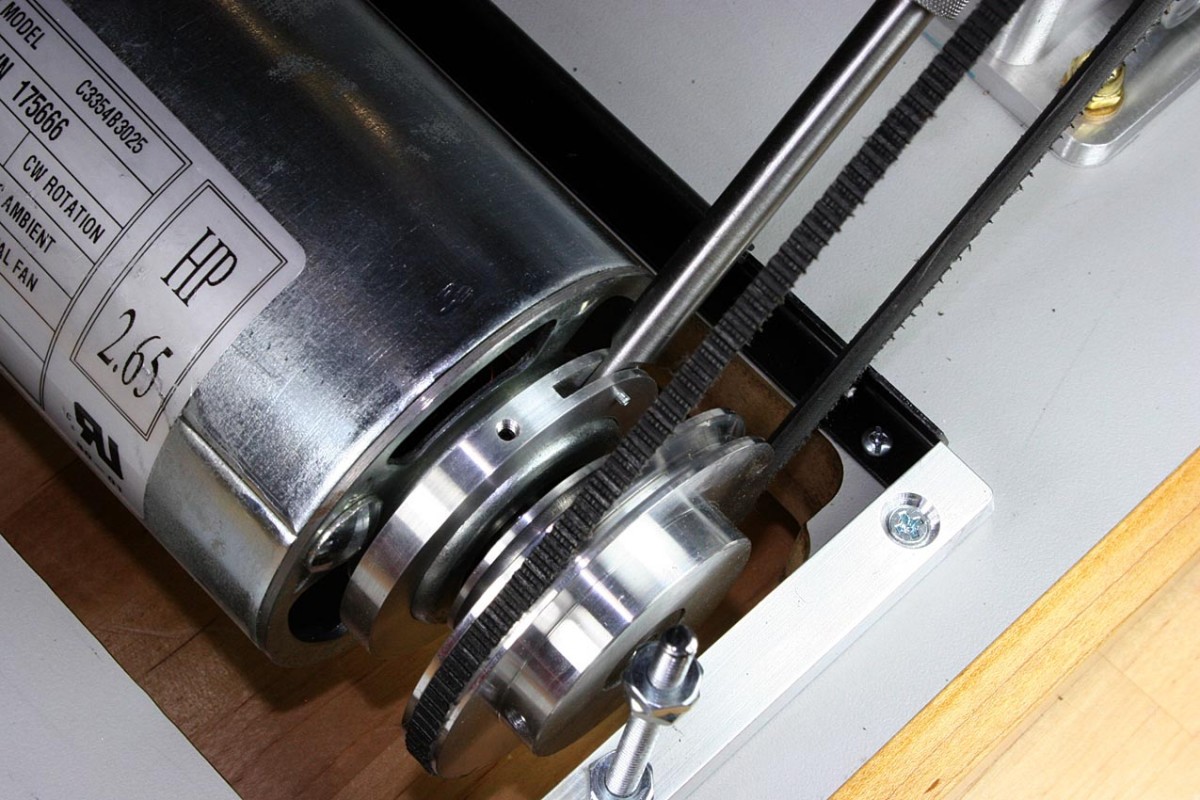
Belt Tensioner – Motor End
The Belt Tensioner – Headstock End
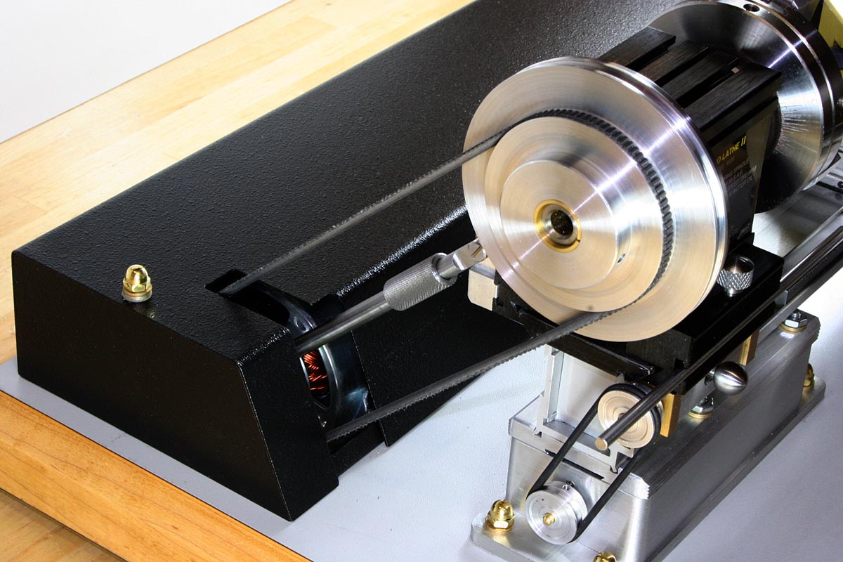
The Belt Tensioner in Context
Headstock End of the Tensioner
The Base
The #1 priority: the whole lathe and drive needed to be portable and self-contained. The second #1 priority was that the base had to be designed to minimize vibration. These two priorities were working against each other; a massive base was preferred to minimize vibration, and for a while I considered making either a cast concrete slab or a welded tubing structure filled with concrete. Ultimately, I couldn’t really grasp how things were going to fit, and wood was easier to modify on the fly than either of the other materials.

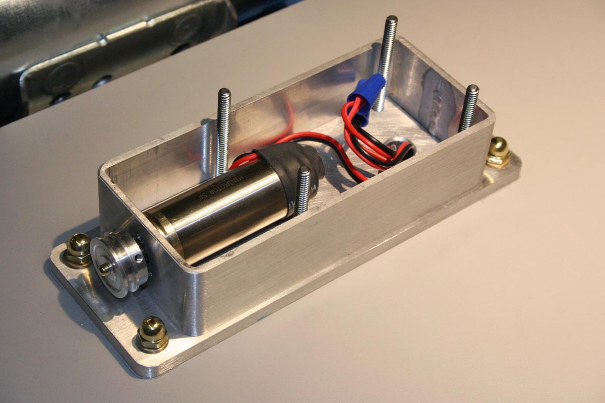
A Powerful DC Treadmill Motor & Controller are Housed Under that Cover
The #2 priority was to make the motor and electronics behind the lathe as protected and low profile as possible. The Taig lathe bed, headstock, and carriage/cross-slide are all loaded with dovetails and T-slots, and I envisioned all sorts of polished and anodized tooling and accessories hanging from my new Swiss army lathe. The only way that the huge treadmill motor was going to work was if the lathe was elevated on a thicker base (which also helps working height) and the motor was semi-buried in the base itself. That’s what I ended up doing, and I like the result.
Several more components ended up partially or fully submerged in the wood base. Aside from the motor, these components had to fit in:
- An MC-40 variable speed controller – this is for the treadmill motor
- A motor choke (necessary for hum suppression because this is a 60Hz motor drive)
- A 24VAC transformer and rectifier circuit for the feed motor and speed control
- Switch/circuit breaker and EMI filter
- Relay and circuit for push-on/push-off motor control and electronic feed-stop
- Pulse width modulated variable speed control for the feed motor drive
- 6 power resistors bolted to the motor plate
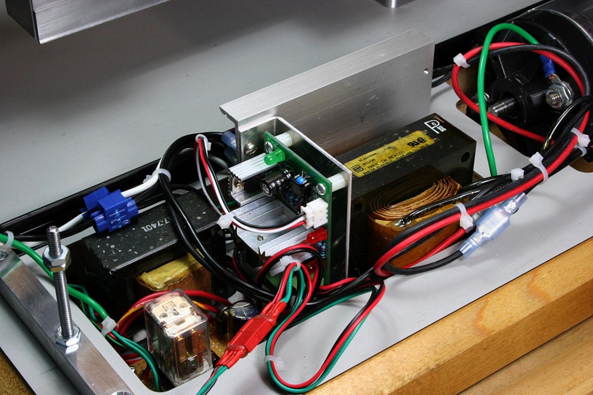
Electronics For Spindle and Feed Motors – Rear View
As the base evolved it became lighter and lighter, ending up looking like several large cutouts surrounded by some wood. All of the electronics were mounted to a 1/4″ aluminum plate flush mounted to the bottom of the base and recessed into a routed cavity. This plate also serves as an exposed extension of the motor controller’s heat sink. The motor cavity in the base is completely open to allow the lowest profile height for the motor and to give the motor a little air circulation. Before edging the base in maple (from my own tree!) the main section was made of two slabs of particle board glued to give a 1 1/2″ thickness. Fortunately I remembered to route in some hidden wiring channels before gluing the boards together, so I didn’t have to route into the base later.
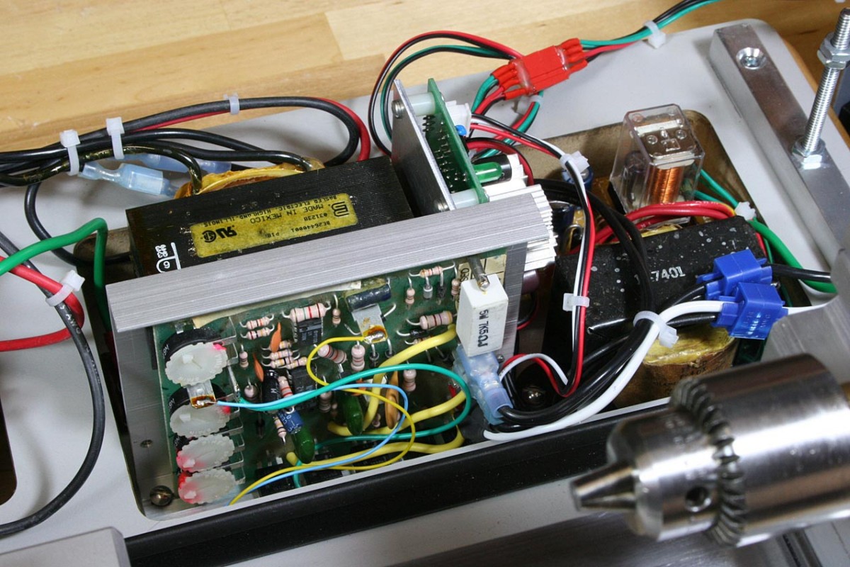
Motor Electronics – Front View
After all of the cutouts were routed and checked for fit, the edges of the particle board were laminated with 1″ maple. Both the top and bottom of the board were then covered with high pressure laminate, and the edges and cavities finish routed.
A last-minute surprise base modification became necessary when I tested the actual Faulhaber mini-motor used for the feed drive. The speed controls that I had bought through eBay had bench-tested fine with just about every motor I had, except they could not go to zero speed with the Faulhaber. I determined that the motor ran on so little current that the controller needed an additional load in parallel to function correctly. One resistor would have worked, but I used what I had, so out came the router again to make some room.
Detail of Cut-Down Motor Mount
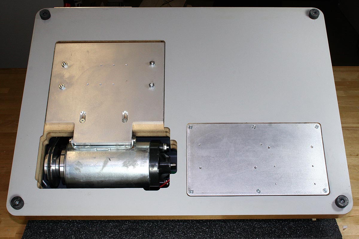
Underside of Lathe Base
Treadmill Motor Partially Hidden in Base Cavity
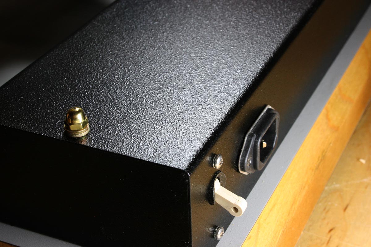
Rear Switch / Circuit Breaker and Power Entry
Adding a Lead Screw and Power Feed
Taig now offers a lathe equipped with a power feed, but it was a little different from what I needed. I wanted a design that used the more conventional half-nut to engage/disengage with the screw. The lead screw also needed to disengage from whatever gear chain or motor that would be driving it. This would allow the lead screw to be hand cranked from the tailstock end, allowing more precise lateral movements than the carriage wheel alone could manage. In short, I needed what John Bentley had already designed.
A few things were done differently:
- The new Taig carriages are made from a solid extrusion rather than a casting: the casting had a hollow cavity in the location where he had installed some of the half-nut mechanics, but that was now solid metal.
- A 1/4″ left-hand threaded rod was used for the lead screw to make the carriage movement more intuitive and to give a .050″ per revolution feed rate
- The 1/4″ lead screw would need to be backed up by a plate or a guide; under load the small diameter of the threaded rod would probably flex and skip out of the half-nut.
- Lateral play between the engaged lead screw and the carriage had to be minimized and easy to control
- Lateral play between the lead screw and the mounts to the lathe bed had to be minimized as well. To this end, I used ball bearings rather than sleeve bearings at both ends. This also eliminated the problem I have of making precision holes that you could pass off as a bearing. I’m not a reamer sort of guy, and any holes I make, no matter how hard I try, are either too small or too big.
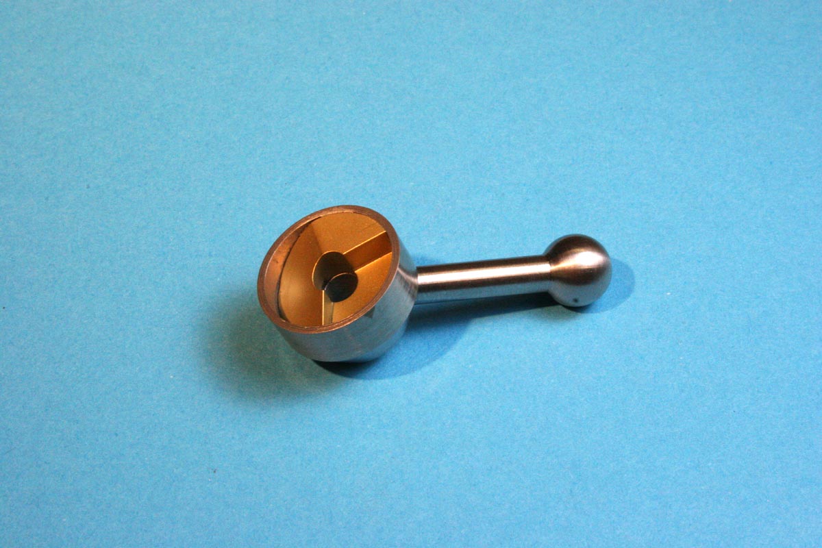
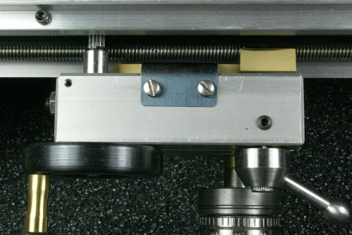
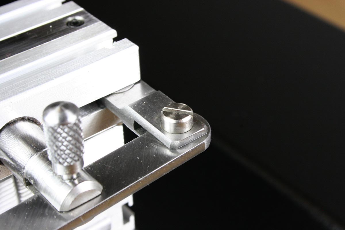
I should mention that this half-nut system really uses only a single half-nut, not two half-nuts that close and hold captive the lead screw. Otherwise, the mechanics are simple. The brass lever that fills the apron slot is free to pivot on the right end. The left end has a short threaded half-nut that is, when not engaged, held clear of the lead screw by a flat steel spring. To engage the drive, the feed knob (actually the short lever on the front of the apron) is flipped clockwise, to the left. This pushes a pin through the apron, which then pushes the half-nut into the turning lead screw.
Here is a short demonstration of the completed power feed:
This is what my finished power feed system looks like:

Clutch Mechanism For Engaging Power Feed
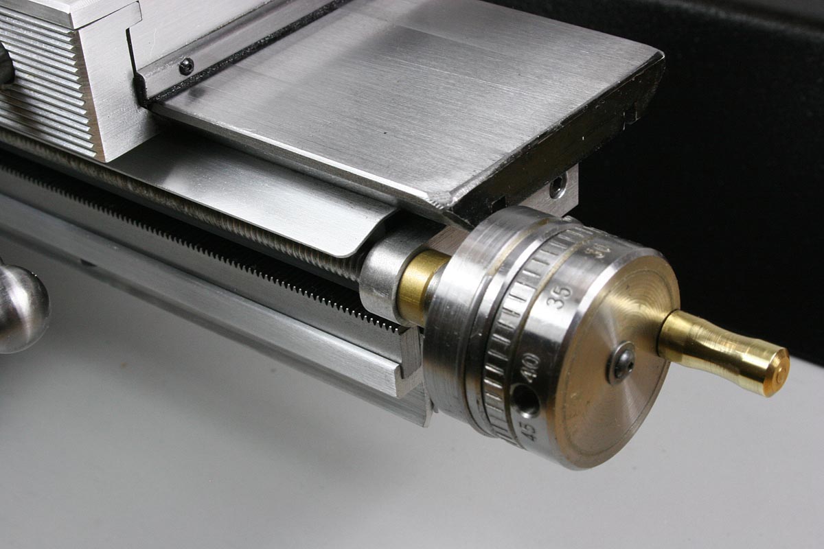
A Modified Cross Slide Dial Allows Manual Feed When Power Drive is Disengaged
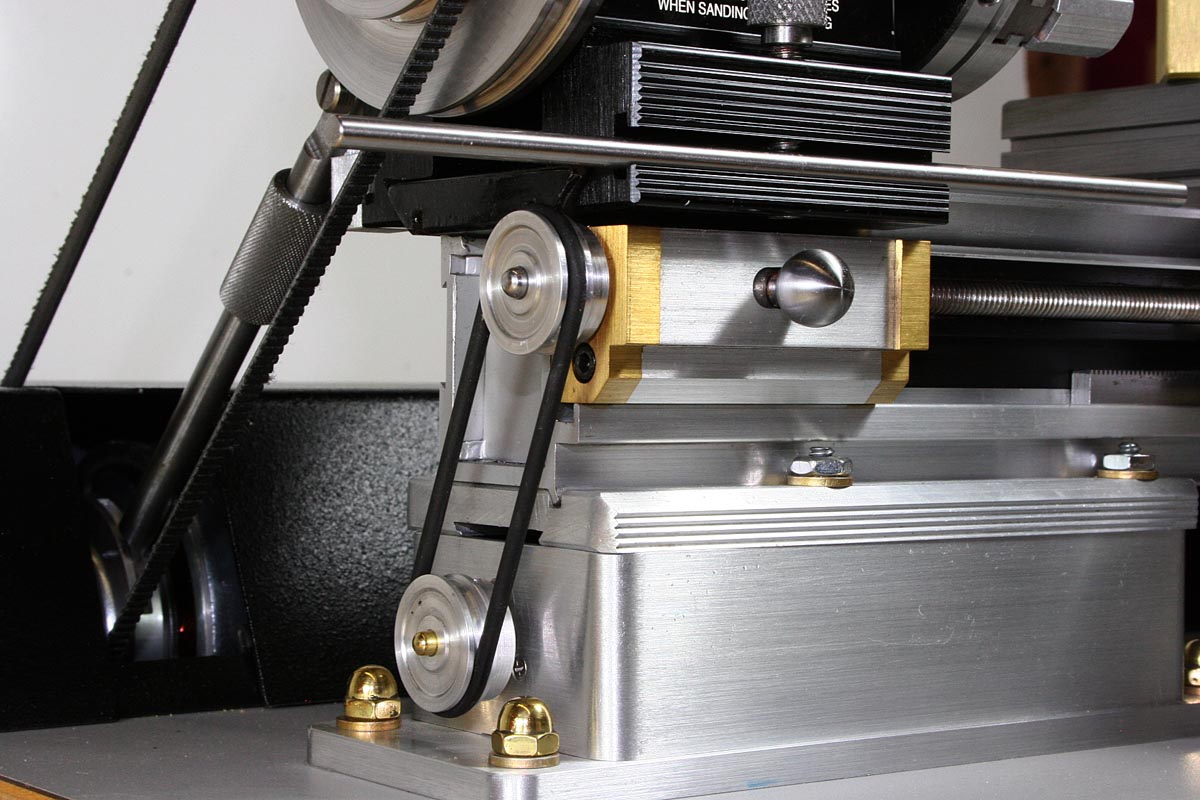
A Variable Speed Gear motor Hidden in the Riser Drives the Lead Screw
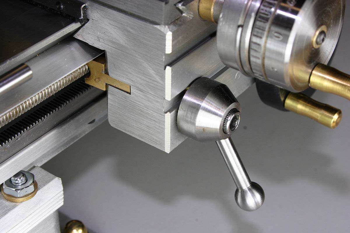
Feed Knob Engages Brass Nut with Lead Screw
The carriage that I received with the kit was, as I said earlier, based on a custom aluminum extrusion that appeared to be cut to length and machined as needed to transform it into a lathe carriage. For whatever reason, there was a 1/8″ slot in the rear face of the carriage apron, facing where a lead screw would go. This was too tantalizing to not use for the half-nut engagement lever, and use it I did.
Rear View of Cross Slide Apron Showing Captive Pivot Pin – Note the Slot. How Convenient!
This slot is used to guide a 1/8″ thick brass lever that pivots at the right end and has a brass half-nut soldered to the left end. A hole for a pivot pin was drilled from the bottom of the carriage and then tapped deeply enough to take a 1/4″ long set screw. Care was taken to make sure that the hole did not conflict with the existing tapped hole than holds the set screw used to lock the eccentric sleeve for the carriage hand wheel and pinion. A steel pin (slip fit for removal if necessary) is dropped in the hole and set screw used to lock it in tight.
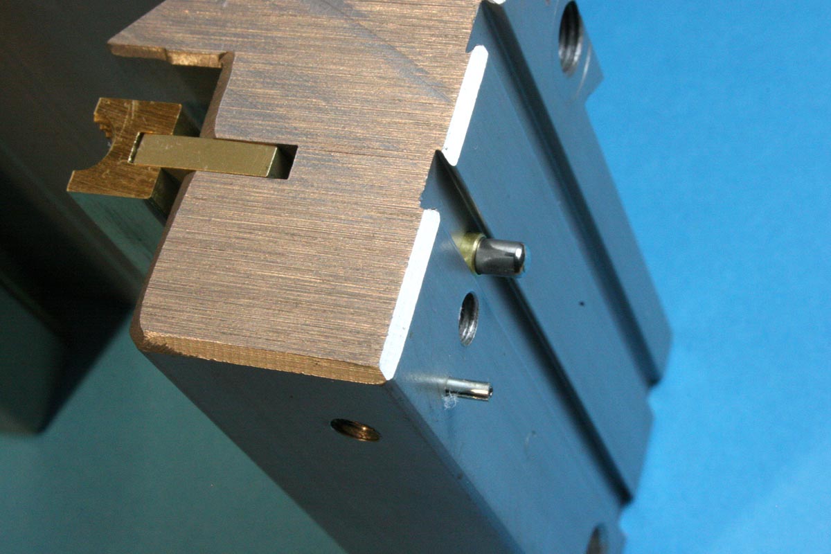
The Large Pin Pushes the Brass Nut Into the Lead Screw
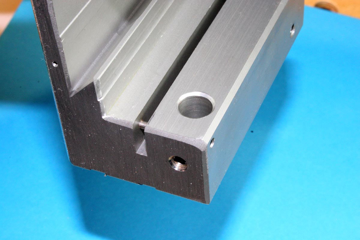
While the carriage was off the lathe, a 5/32″ hole ( because I used a brass sleeve for a 1/8″ pin) was also drilled at the left end of the carriage from the front of the apron, in line with the magic slot and about 1/4″ deep into the slot. This acts as a guide for a pin that would push a lever in the slot toward the lead screw rod. This hole was located at the correct height to end up exactly in line with the center of the slot, which meant it had to be drilled from a point that was not quite centered in the bottom of the small dovetail slot on the front of the carriage extrusion.
Although I drilled more holes later after I had made the carriage half-nut lever and feed knob, I’ll describe them now: Directly underneath the hole drilled for the sleeve and the pin (that pushes the half-nut lever) there is also a 10-32 tapped hole for a socket head screw about which the feed knob rotates, and a tapped bottom hole that allows a set screw (with a brass slug to prevent thread damage) to lock that 10-32 screw. This allows the 10-32 screw to be easily adjustable from the front to set precisely how far the half-nut gets pushed into the lead screw. Once the 10-32 feed handle pivot screw is set, the bottom set screw locks it in place. This provides a very simple method of adjusting for half-nut wear and for setting the lead screw backlash to nearly zero.
The tapered slot in the end of the brass half-nut lever was an idea I had to eliminate any lateral play that could occur from an oversize or worn hole in the lever at the pivot pin. The pin size and the slot taper were matched so the taper straddles the pin around the middle, without the pin being in danger of bottoming out in the slot. The half-nut lever is pulled back to the disengaged position, and the tapered slot held tight to the pivot pin, by an “L” shaped strip of spring steel screwed to the bottom of the apron. Very simple, very effective.
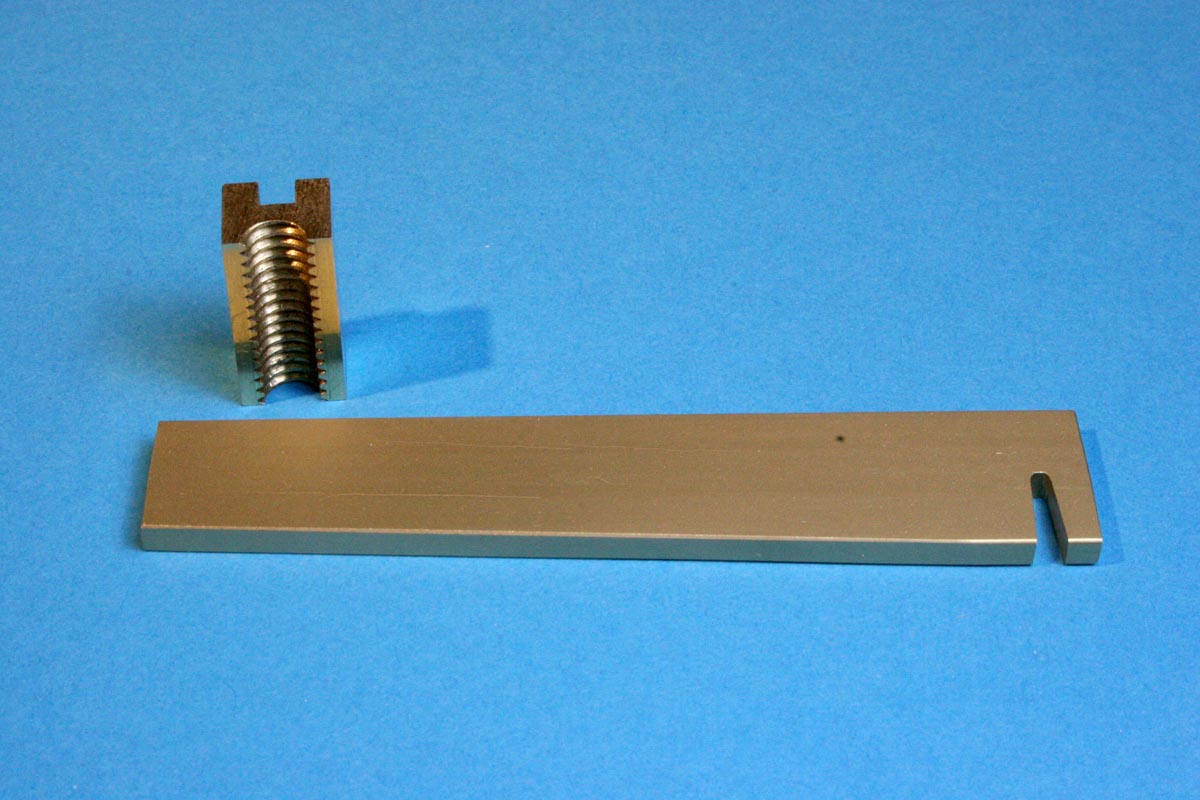
Parts for Half-Nut Engagement Lever
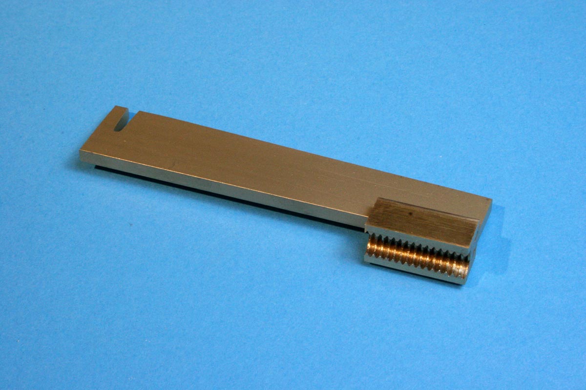
Parts for Half-Nut Engagement Lever Assembled
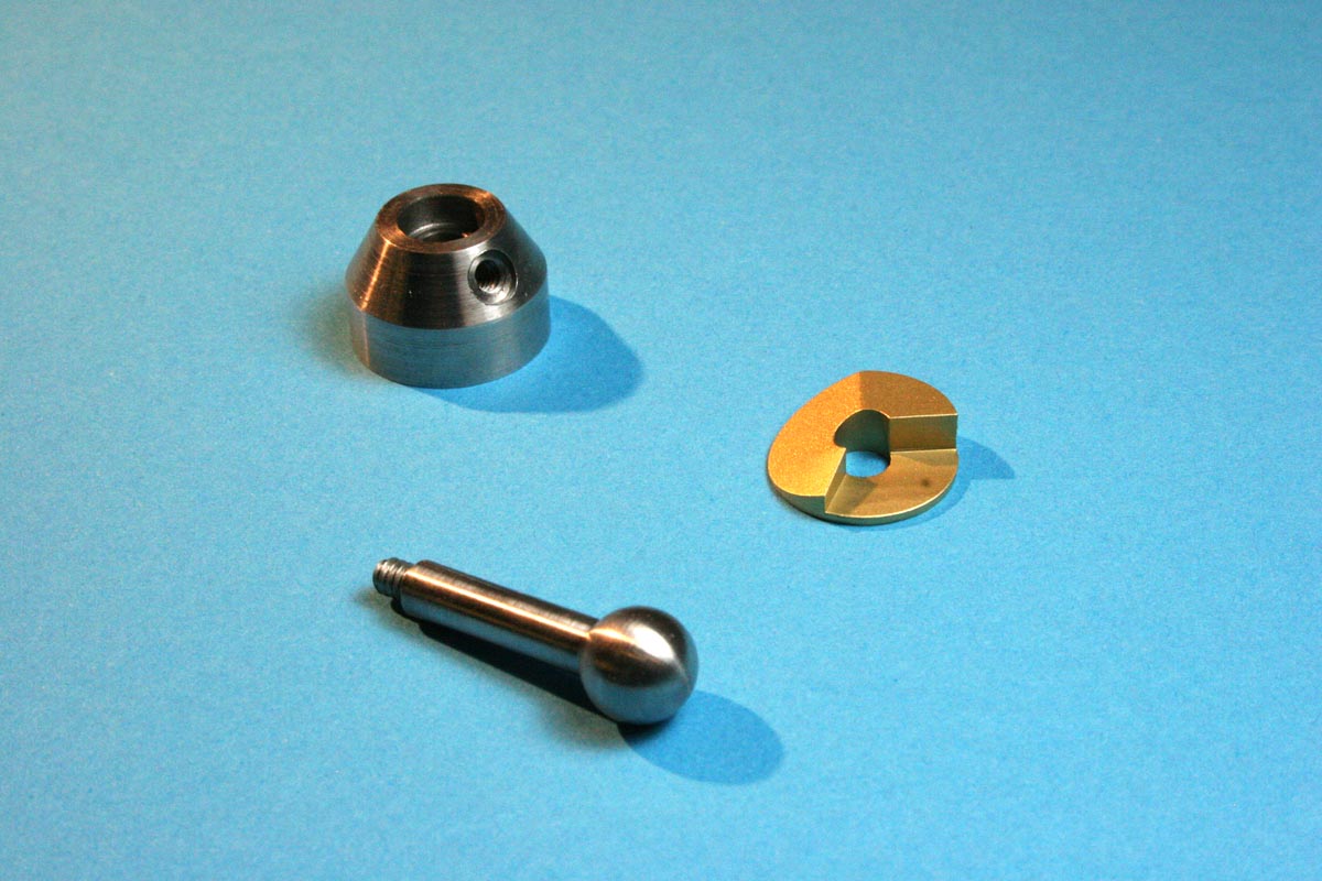
Feed Knob Components
Feed Knob Components Soldered Together
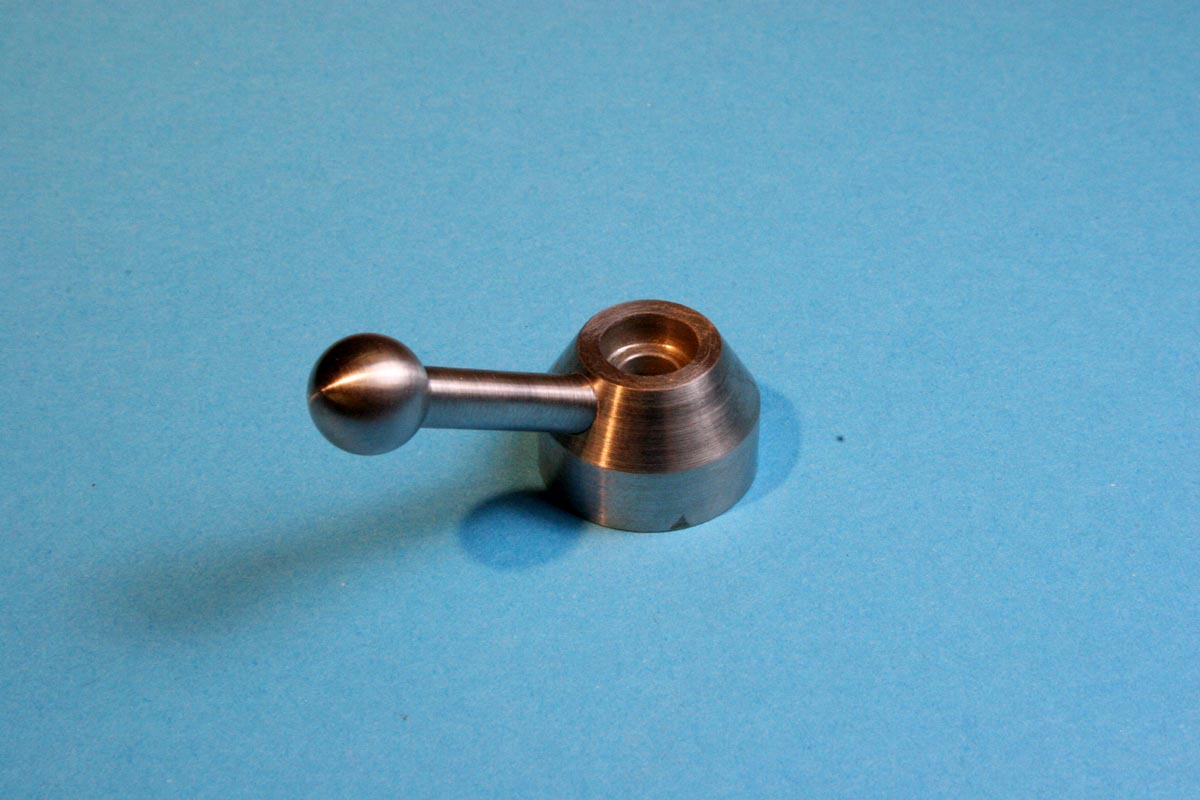
Feed Knob Front View
Half-Nut Engagement Lever in Front Apron – Fully Disengaged Position.
Feed Disengaged – Not Much Movement Needed
Bottom of Carriage Apron – Feed Engaged
The Lead Screw Clutch
This is another Bentley design that was so nicely done that there seemed to be little need to do anything except build it. Some changes did have to be made, primarily to accommodate the different carriage design, to incorporate ball bearings (to handle the belt load of my power feed drive), and to change the engagement dog design to something better suited to my more limited machining skills.
The principle is simple. The drive shaft has a half-flat section on its end, as does the driven shaft (lead screw). While the drive shaft flat is long, the driven lead screw flat is short, and the ends are separated a short distance. A very short coupling section consisting of a shaft with a long flat on one end and a short flat on the other resides in the gap and is free to slide horizontally. Because of the long flats, the coupling shaft is always rotating along with the drive shaft as long as the two stay engaged, and the coupling section movement is constrained to always keep it engaged at the long-flat ends. As soon as the coupling section moves toward the lead screw, the short flats engage and the lead screw now begins to rotate. The coupler shaft can be move left and right while rotating by means of a stationary fork or pin running in a circumferential groove on the shaft itself. It’s very simple and positive.
The flats can only engage when lined up correctly, once per revolution, so a slow rotation of the drive shaft requires that you apply pressure to the coupler for some time until the flats are lined up and the coupler slides into the locked position.
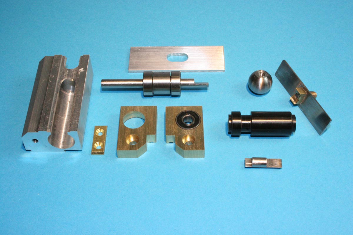
Components of the Clutch for the Lead Screw Power Feed
In the photo above you can see that two ball bearings were used for the drive shaft and a single ball bearing was used in one of the brass end blocks to support the left end of the lead screw. Rather than have the very short coupler shaft (lower right in photo) slide in metal, and since there was not much bearing surface, the shaft was pressed into the black acetal sleeve that can be seen above it. The bore of the sleeve is tighter in the center to hold the coupler shaft, and a little looser on the ends so that it is a sliding fit on the drive and driven shafts. The brass block protrusion on the stainless plate (upper right of photo) rests in the groove of the rotating acetal sleeve to move it left (disengaged) or right.
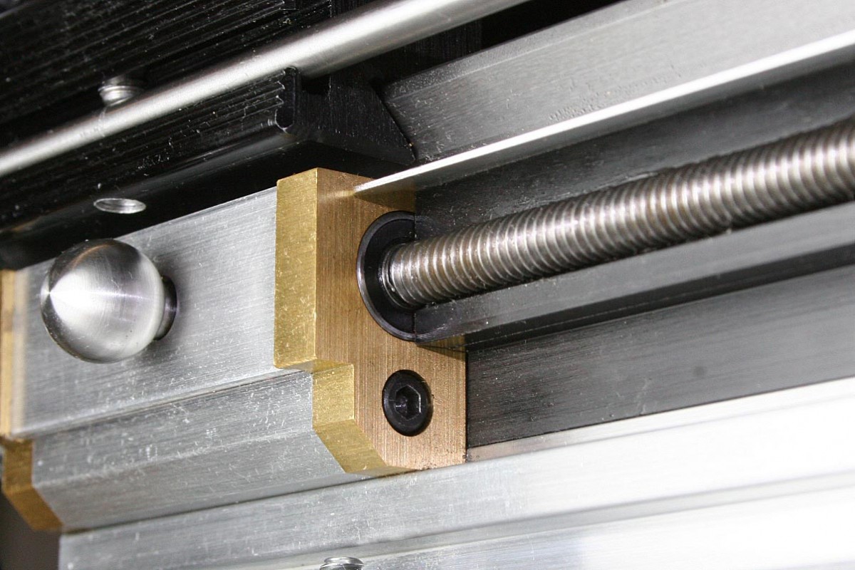
Nothing was terribly critical in the fabrication. For .187″ shaft diameters, a short flat length of .190″ and a long flat length of about twice that or .380″ seemed to work out. The shafts all needed to align, and it helped to bevel the ends of the flats so the engagement was not so fussy. The housing block on the left was dovetailed on the back (bottom in the photo) to slide into a dovetail channel in the front of the lathe bed. A single set screw pushes the block tight into the dovetail. There are no holes drilled in the bed, and the whole assembly can be removed in about a minute.
Lead Screw and Support Plate
The lead screw material is nothing fancy, just 1/4″-20 LH threaded rod. All I needed was about 12″ of good stock. Unfortunately out of the 12 feet of stock that I ordered from Enco I got nothing usable. The quality of the pieces varied a lot, but it was all pretty bad, more suitable for light duty re-bar than anything else.
Some lengths of low carbon and 4140 rod were then ordered from McMaster, and they looked much better. The low carbon stock had the best surface finish, and the best sections were polished in my other lathe using a threaded metal lap. The ends were turned down to fit the bearings on each end and the left end was machined with a flat to mate with the feed clutch described above.
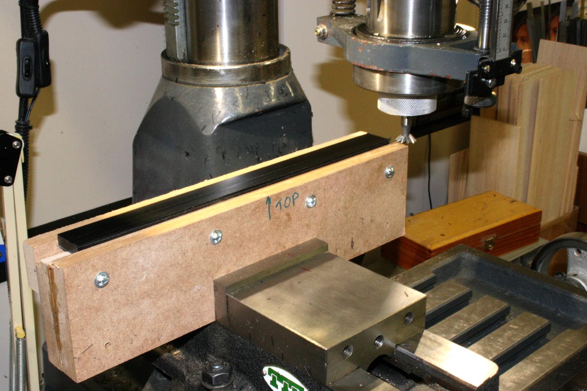
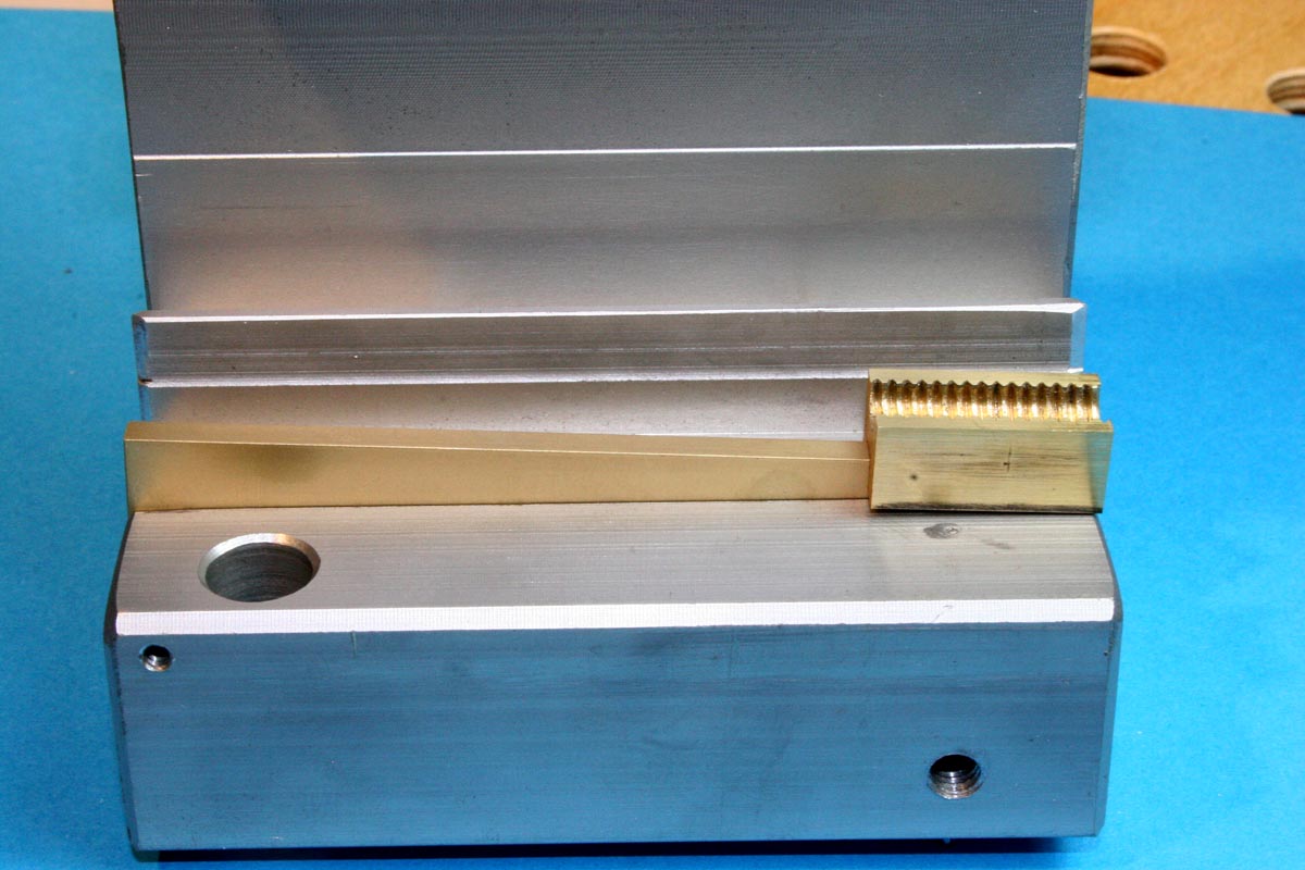
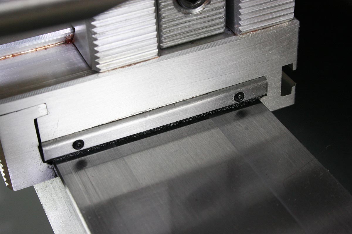
MDF Clamp for the Acetal Lead Screw Support. The Clamp Never Left the Vise.
As mentioned earlier, the use of such a small threaded rod required the use of a backing plate on the bed of the lathe to support the lead screw against the half-nut when engaged. A strip of acetal was machined to slide into the dovetail channel on the front of the lathe bed and at the same time provide a cylindrical groove for the lead screw to lie in. The lead screw position was fixed relative to the dovetail; nothing was adjustable, so the acetal strip had to be made accurately. An MDF clamping block was made for the milling machine so
Closeup of Plastic Lead Screw Back Support
that it could initially hold the raw plastic strip for facing, and as the plastic was machined the MDF could be machined as needed to clamp the changing profile. All of the plastic machining operations had to be completed without removing the clamping fixture from the vise. It worked, and everything came out fine, but it really was more difficult than necessary.
If I had to do this all over again I think I could have accomplished the same end result by drilling and screwing a strip to the front of the lathe bed, without using the dovetail.
As it turns out, it is unwise to assume that the aluminum extrusion that forms the lower part of the lathe bed is exactly parallel to the ground steel bed. The extrusion self-aligns in two grooves in the bottom of the steel bed, but for whatever reason the clearance between the carriage apron and the front of the aluminum extrusion varied by about .014″ over the length of travel. I fixed this with a light fly cut on the back of the acetal, but a simple strip screwed to the front could be shimmed or shaved easily if you should encounter the same problem. A quick test of parallelism running up and down the bed using a dial indicator on the carriage would have saved some trouble, but it was a problem that was not anticipated.
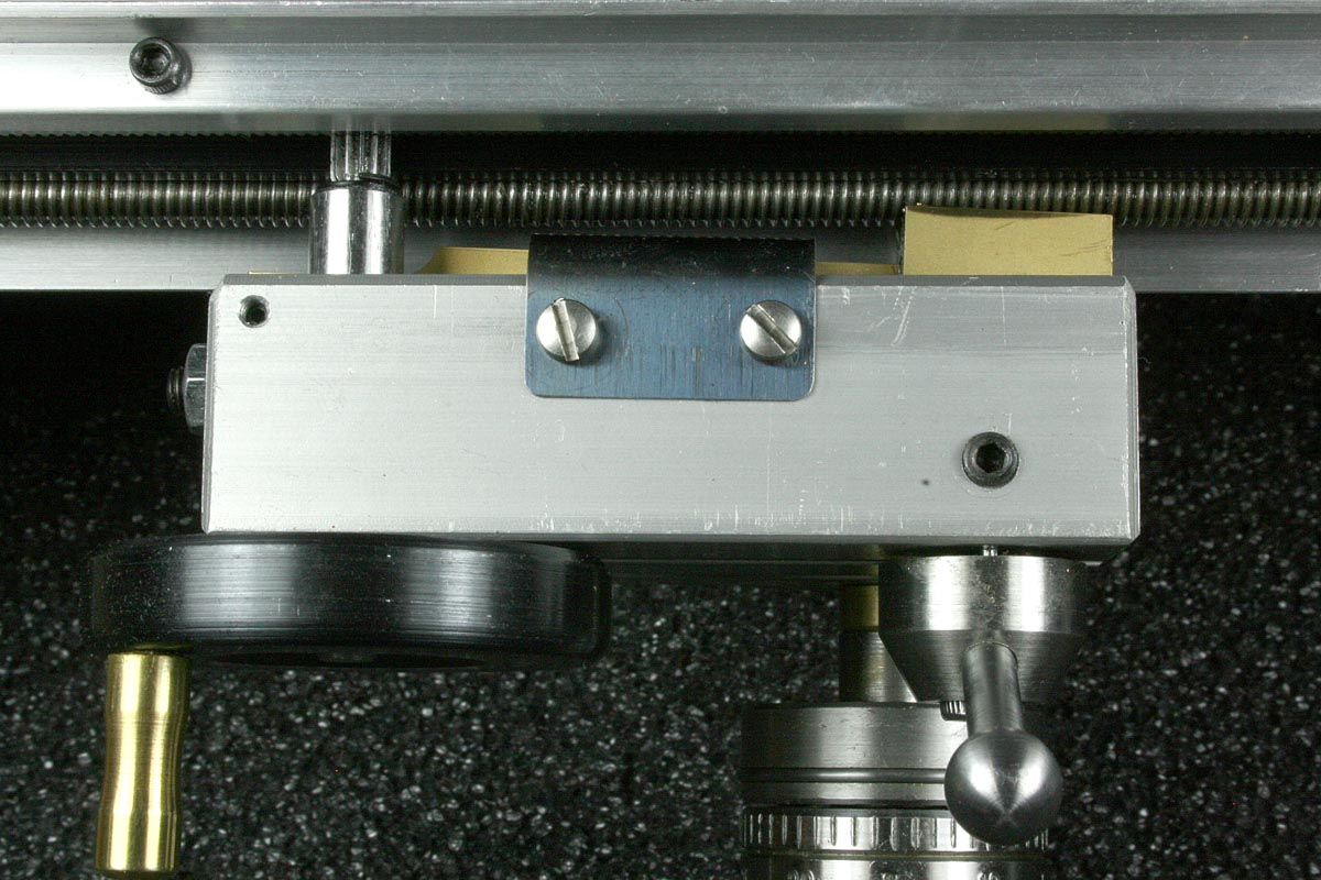
An unexpected side benefit of having the plastic lead screw support is that it made the installation of a chip cover over the lead screw extremely simple. The narrow gap between the top of the plastic and the underside of the extrusion feature that holds the rack gear was perfect for retaining a thin aluminum strip bent into the form shown in the photo. You can’t see it, but the back side of the aluminum strip has a 90 degree bend, forming a flange about 1/8″ wide. The upper rear edge of the plastic is relieved (a small rabbet cut) to make room for the flange. The aluminum strip is installed by simply sliding it into place from the tailstock end. You do have to remove the screws and drop the hand wheel on the end of the lathe to allow clearance.
The Power Feed Drive Motor
For a while I debated whether or not I wanted to be able to cut threads on this lathe. I didn’t want another change-gear type of lead screw drive (my Logan has change gears).
I initially planned to use a Faulhaber gear motor that has an integral encoder wheel on the motor shaft – prior to gear reduction – that would give considerably more position accuracy than I would ever need for threading. A pair of optical sensors positioned correctly in quadrature on the headstock could count the holes in the index wheel on the spindle pulley. Along with a once-per-revolution index, the sensors signals could easily be processed by an Arduino, or more likely a PIC microcontroller, to yield both direction and rotational position information. This would be directly translatable into any thread pitch you want to dial in. A stepper motor would be a little easier to use for the lead screw drive, but I wanted something smaller to fit in the riser base, hence the plan to use the analog servo approach. A chain or gear drive would couple the motor to the lead screw.
Big plans, and then reality. This entire micro-lathe project was already a tangent to what I was trying to accomplish (what was the point, by the way?). Projects nested too many levels deep are a constant problem, and I decided to go with a simple variable speed power drive. If any time is going to be spent on a programmable thread-cutting design, it will be for my larger lathe.
I already had several gear motors that would work for the feed drive, and it was just a matter of deciding on a pulley ratio that would give the right carriage speed at the motor’s rated RPM. For a speed control, I found several different types on eBay that looked like they would work, and for $8 to $10 I wasn’t even going to think about designing something. I ordered a couple different types, and they both worked very well. They were very nicely made, with high quality PC boards, and I picked one that seemed to provide a little bit of torque feedback.
Gear Motor for Power Feed
Earlier I had made a solid aluminum riser for under the lathe’s mounting base, but I decided that this would be a good place to hide the motor, so I started hogging out metal. After a while it became apparent that this was going the wrong way, so I built a hollow riser from a strip of 1/8″ aluminum flat folded into a rectangle and welded at the seam. This has worked out well and provides space for the wiring. Overall, I am very happy with the variable feed drive.
The feed motor is tied into the spindle motor relay, so that the feed turns off with the spindle. I also put a headphone jack on the motor cover for a connection that stops everything when shorted. The plan is to have a moveable, dovetail-mounted contact on the rear of the bed that can be set up as a stop. As soon as the carriage hits the stop contact the spindle and feed motors stop.
Re-bushing the Carriage Hand Wheel Sleeve Bearing
NOTE: This problem is only relevant with power feed.
Setting the rack and pinion gear clearance was not a difficult task, although I did find a need to drill and tap for a second machine screw to pull the rack tight into the bed extrusion. I’m not sure why it comes with only one screw point – my rack had a slight upward bow to it, enough to make the carriage hand crank tighten up a little at the right end. The problem with the carriage hand wheel became apparent when the carriage was pushed or pulled along the bed as a lead screw would – the hand wheel pinion would always find a spot to bind. I tried all different lubricants and gear clearances, and nothing changed the binding.
After some examination it became apparent that the pinion and the hand wheel did not like to be driven from the rack because of binding in the eccentric sleeve bearing. There was nothing wrong with the parts; this was a metallurgy problem between the pinion shaft and the bushing, aggravated by the fairly high rack-to-pinion gear ratio that put a high side load on the pinion shaft when the carriage was pushed. I concentrated on trying different lubricants for the bearing, to no avail. Once a rough spot was encountered, the side force on the pinion would jam it even more, and damage would occur if continued.
Eccentric Bearing Bored Out and Fitted With Acetal Inserts
After trying some test parts it seemed that a plastic bearing surface would work better. In order to keep the contact area (and the friction) low, the original steel eccentric bearing was mounted in a 4-jaw chuck and the center bore was dialed in. It was then bored out a little oversize all the way through, then the ends were bored 1/8″ deep to the largest diameter possible without excessively thinning the wall. Two tiny acetal flanged sleeves were machined to fit the bored ends and provide a good bearing surface for the hand wheel pinion gear shaft. This apparently fixed the problem, because the hand wheel would now spin freely when the carriage was pushed.
Bed Wiper on Tailstock
Bed Wipers
Wipers to prevent debris from getting under the carriage and tailstock were made from .020″ steel strips with a 90 degree bend on one edge to stiffen them. Thin leather strips were cut to act as wipers. Two 0-80 button head screws hold each of the four bed wipers in place. The tailstock wipers were probably not necessary, but they’re on there now.
Tailstock Lever Modification
Clearly this is another stolen design, but with the requisite changes made just to be different and to change the geometry of motion.
The tailstock lever is probably one of the more commonly modded parts of the stock Taig lathe. As supplied the lever is serviceable but leaves much room for improvement. The hand lever and two formed pieces that comprise a pivot fork are fabricated from flat steel strips. The lever is short, and even on a small lathes like this the force required for tailstock drilling can require more hand pressure than is comfortable. Functionally, the short length of the hand lever and pointed corners that poke the palm of your hand are the main shortcomings. There is room for aesthetic improvement as well.
The photos tell the story – all of the flat steel parts were replaced with 12L14 machined parts, and it is somewhat nicer to use that it was originally. Note that to obtain a full range of motion to the left, the lever does need to be thin enough to freely enter the slot in the tailstock extrusion.
New Tailstock Lever
Closeup of Pivot Fork
Reinforcement for Tailstock Clamp
This can be seen in the left image above.
The bore in the tailstock for the sliding dead center spindle is cut very close to the base of the T-slots and channel above it. So close in fact that the curvature of the bore can be seen as deformation in the base of the slots. Locking the center spindle with the supplied machine screw could potentially bend the top of the tailstock extrusion over time.
A simple piece of steel bar stock was milled to fit into the center channel, and secured at the rear with a recessed socket head screw. Now a slightly longer socket head screw (or lever as show above) clamps down on the bar, which in turn presses directly on the spindle, providing a more positive lock without the risk of bending anything.

Etched Aluminum Control Panel
Etched Aluminum Control Panel
I wanted the motor controls to be located clear of chips and where there would be no need to reach over a spinning chuck. Shortly before I started working on the lathe I had finished a couple projects that had required photo etching both copper and aluminum. I thought a photo etched panel for the controls would be nice because it is a relatively easy way of creating sharp text and graphics and the recessed graphics are more durable than surface printing would be.
The .080″ thick aluminum was formed first, punched, and then brush finished. The artwork was created using Photoshop and a negative was printed on a transparency film. The photoresist sheet (I use PurEtch photopolymer) was applied to the surface, dried, and exposed to UV through the negative artwork. After developing, the plate was etched in the same ferric chloride etchant that is used for copper-clad printed circuit boards.
After the graphics were etched deep enough to hold paint, the panel was cleaned of all resist film. A little black enamel was dabbled into the etched areas, and the excess paint was squeegeed off using a business card. Areas away from the graphics that could be safely wiped were cleaned with solvent. The paint in the etched recesses was allowed to dry overnight.
Final cleanup was done using a thin, lint-free linen type of cloth. A small square of cloth was spread flat on a non-absorbent surface and wet with a couple squirts of lacquer thinner. The panel was then rubbed around on the flat cloth until all of the paint film remaining on the surface of the aluminum was cleaned off, leaving only the recessed painted graphics.
As a final step a couple very thin coats of clear acrylic were sprayed on the cleaned panel.
Final Thoughts
Looking back at the modifications that were made to the Taig, I have to remind myself that most of these were enhancements that I wanted to make, and were not essential to the functionality of the basic unit. This lathe will no doubt be an ongoing project, but even as it stands it is a better choice for me than a Sherline or Unimat, both of which I would be less inclined to modify. The kit (or even the factory-built version) requires a little effort to get it going, but it is a surprisingly solid and competent machine for its size, and I would make the same choice again.
![]()