A Homemade Progressive/Universal RF Coil Winder
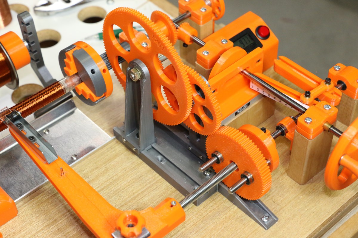
The mostly-completed progressive/universal coil winder. The universal portion is my adaptation of Morris Coilmaster design with some added features. The progressive feature is new. All parts were designed in Fusion360 with the exception of the very nice 3-jaw chucks posted by user “mdkendall” on Thingiverse.com (link in text below).
A few years ago I became fascinated (obsessed) with theremins to the point that I’ve ignored maintenance of this website and I’m pretty sure I can’t even play guitar anymore. The theremin is a miserably difficult instrument to play, but in the early morning hours when no one else can hear me I find a deep satisfaction in playing a musical instrument that almost seems to be connected directly to my brain. If you can think of a melody you can play it (how well you can play it is another matter).
It’s strange that I resisted the theremin for so long in my younger years. It is a natural fit in that it is an electronic instrument that uses radio frequencies and oscillators and filters, all stuff that I’ve been into since my pre-teen years. The theremin story is for another time, though. This project, a coil winder that allows one to make high-frequency coils with winding patterns that are impossible to do by hand, is actually a side task for a theremin construction project that I’ve managed to stretch out for over a year now. The theremin is called a Melodia and was designed by the late electronic-music pioneer Robert Moog. It was one of several theremins that he designed and produced over the years, and this particular one was as I understand offered in kit form as well as being factory produced. Since it is a sixties-era design it uses many components that are no longer available including the inductors and transformers that need to be either carefully hand-wound or machine-wound.
Even though my main motivation for taking on this project was to make a coil winder for theremins, this type of device has wider use in the areas of amateur radio and any other hobbies that venture into HF, VHF, and UHF frequencies. In fact an inexpensive device called the Morris Coilmaster was available from electronics vendors such as Allied Radio in the 1960s. Part of my winder is based on the Coilmaster design but it has added features of a coil width adjuster and progressive feed specific to the needs of my theremin project.
The Morris Coilmaster consisted of a bare-bones cast metal base, stamped gears, and a simple worm-gear driven turns counter. Today they are collector’s items. Scanned from a 1965 Allied Radio catalog.
About Coil Inductors and Winding Patterns (a little technical, but math-free!)
Example of a universal winding pattern; 1/2″ Core, AWG 36 enameled & cotton-covered wire. The cam shaft-to-spindle gear ratio here was 39:44 resulting in the very open spacing of the windings.
Inductors, like all real world circuit elements, can have extremely complex models depending on the frequency of use. For very low frequencies it might be sufficient to model a real inductor as a pure inductance with a series resistor that represents the DC resistance of the wire. As frequencies increase, more elements need to be tacked onto the schematic to adequately model behaviors that aren’t explained with the simpler models.
When fabricating a high-frequency inductor the problem with simply feeding wire neatly onto a form to reach a specified inductance is that each turn of wire in the coil is capacitively coupled to adjacent turns, and this can have a major effect on the behavior as frequencies increase. This coupling occurs on both sides and above and below a given wire if multiple layers are used. These multiple parasitic capacitances can complicate the equivalent circuit for the inductor, changing it from a simple ideal inductance into a series of incremental inductances interspersed with incremental parasitic capacitances. When inductors carry alternating current adjacent turns in the coil will be at different potentials (voltages), and these potentials across the parasitic Cs will result in unwanted “shortcut” displacement currents that circumvent the desired current path which ideally would run directly through the wire. Parasitics can impair performance and actually become dominant, making the inductance look like a capacitance above what is known as the self-resonant frequency (SRF).
The self-resonant frequency is a crossover point at which the inductor ceases looking inductive and is on the verge of behaving like a capacitance if frequency increases. In fact the SRF is defined as the frequency at which the inductive and capacitive reactances are equal. At the SRF the complex impedance of the coil is purely real (resistive) with no imaginary (reactive) component. The value of that resistance at the SRF represents all the losses in the coil due to resistivity of the wire, skin effect (where current density within the cross-section of the conductor carrying AC ceases to be uniform), dielectric losses in the winding core or supports, eddy current losses, radiation resistance, and more.
Many interesting winding techniques have been developed to minimize inter-winding and end-to-end capacitance . The goal is almost always the same: try to figure out how to wind the required number n of wire turns (ideal inductance is proportional to n2) in the given volume while keeping the individual turns as separated from one another as possible. Most importantly the coupling between the ends of the coil which have the largest voltage differential must be kept to a minimum, so in general the current should progress through the coil in one direction without any looping back. Obviously this eliminates the traditional multilayer solenoid method of winding where wire is close-wound down the length of the core and then jumps to a new layer and is wound back to the starting point, and so on. When it comes to priorities, the layer-to-layer or end-to-end spacing of windings is more important than turn-to-turn spacing, because there exists a larger complex voltage gradient between points within the inductor that are further separated.
Coil Winder Design
Closely spaced parallel wires exhibit the greatest capacitive coupling, but this coupling is greatly reduced if the windings avoid parallel runs and instead cross one another at an angle. In this case the parasitic C is small because the electric field lines are only clustered around the spot where the wires cross. The universal winding method, also know as honeycomb winding, places wire on a core in a criss-cross pattern where each wire on a given layer crosses the winding below at an angle to minimize coupling between layers. If the density of turns within a given volume is not terribly critical the helix angle of the winding can also be adjusted to provide increased turn-to-turn spacing as well.
This all-mechanical universal coil winder has a feed arm that is forced to move laterally by a rotating cam as the inductor core rotates, feeding wire onto the core in a helical path before reversing direction at the end of its stroke. The cam rotation is geared to the headstock spindle through user selectable ratios. For example, the Morris Coilmaster winder had a standard gear set of 39, 40, 42, and 44 teeth, and changing the gear ratio between the cam shaft and the spindle shaft changes the helix angle of the windings and the spacing between wires. The cam is generally designed to provide linear movement of the feed arm in both directions, although some other DIY winder designs use a circular disk or large washer set off-center on the cam shaft to provide sort of an asymmetric sinusoidal movement.
My design adds the option of introducing a slow lateral feed in addition to the standard reciprocating motion of the feed arm. This is accomplished through a set of reduction gears that link the spindle rotation to a lead screw that slowly moves the feed arm down the length of the core while it is reciprocating at a much faster rate. This is the “progressive” part of what is now called a progressive/universal winder. This spreads the universal wind over a desired length, further separating the two ends of the inductor and raising the SRF by minimizing the inductor’s end-to-end capacitance.
A progressive/universal coil wound on this machine: 1/2″ I.D. Core, 1200 turns AWG 38 magnet wire, helix width 0.112″. Inductance is 75mH when ferrite core is inserted
This coil winder design is all very experimental and is a work in progress. Prior to building this I had been on the fence on whether to build an Arduino-based stepper motor winder or go all mechanical as I did. I do like mechanical contraptions, but when it came time to explore progressive winding I wished I had given more more consideration to the ultimately more versatile electronic version. My main reason for avoiding it was to avoid loss of feeling for winding very fine wire. Starting a winding can be a touchy process which favors the use of a hand wheel to feed a little bit at a time, and without some fairly sophisticated tensioning and shock absorption features built into the wire path a stepper motor would simply overwhelm and break fine wire.
The Contraption
NOTE: Since this is a work in progress and all of the part files are a mess I have no plans to publish them on Thingiverse. In addition, there was a fair amount of lathe and wood work involved that take it beyond an all-printed project. This article is being written to offer ideas for your own design based on your own capabilities and available parts.
The best way to describe the operation starts with a video:
All of the 3D printed parts for this winder except for the 3-jaw chucks were designed by me in Fusion360 software and printed on either a modified Creality CR10S Pro or Prusa MK3S printer using Overture Orange and Space Gray PETG filament. The cylindrical linear bearings (qty 3) are 6mm I.D., and the linear rail bearing used for the cam follower has a 2″ travel range of which only 1″ is used (manufacturer is Del-Tron but I have no part number). All other bearings are brass sleeves made by cutting lengths of K&S tubes available at hobby shops.
The chucks shown below solved a problem that I had been pondering for some time about how to grip all types of coil forms. I came across this chuck design by user mdkendall on thingiverse.com and was very happy with the first-time fit of all the components. I had to design some threaded hubs in Fusion360 to fit and adapt to the 1/4″ shafts that I used. The only issue I have had with the chucks is that I think the slots on the side of the jaws could be tightened just a little to prevent the jaws from rocking under pressure. Otherwise, it’s a great design and these chucks could be useful for a number of light-duty applications. I did replace the printed snap ring with the steel one visible on the backside of the left chuck. The plastic one kept popping out.
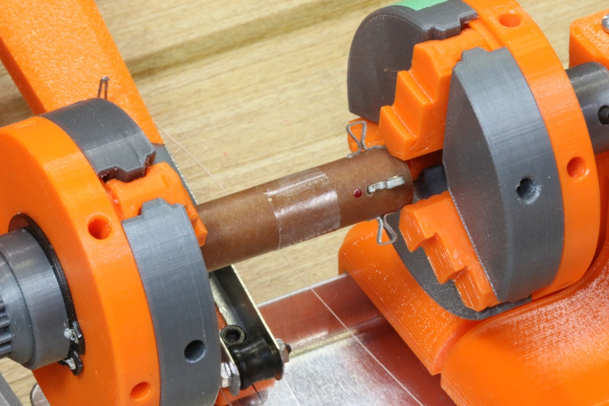
A homemade phenolic core being prepared for winding. A layer of double-sided adhesive tape is a great help for keeping the first layer in place.
The picture below shows a closeup of the cam (with the pointed end in the top position), cam follower, and the variable stroke adjustment arms.

Variable stroke mechanism for reducing the 1″ cam follower movement to whatever coil width is needed.
The vertical shaft in this picture is the main drive shaft with the crank handle mostly cut off in the lower right corner. The heart-shaped cam located just to the left of the counter display rotates with this shaft and pushes the cam follower plate (the part with the long horizontal slot) left and right. The arm with the calibration marks attached to the cam follower plate is fixed at the lower end so that the arm swings left and right at the top end only.
A dog-bone link connects the swinging arm to a nearly identical but perpendicularly-fixed arm to its right. This second arm allows the leadscrew shaft to rotate (only when the progressive feature is used) while it pushes the shaft left and right on linear ball bearings. The dog-bone link slides and locks in dovetail slots in both arms during setup to allow adjustment of the lateral stroke of the lead screw shaft from zero to the full one-inch stroke of the cam. The position of the left end of the link is critical to determining the stroke of the feeder and hence the width of the coil; the only requirement for the position of the right end is that it allow the link to be roughly perpendicular to the driven arm when the swinging arm is parallel to it. This minimizes geometric errors as the full stroke of the cam is scaled down to a width suitable for the desired coil.
This picture shows a better view of the back side of the cam follower plate:
Ball bearings on the cam follower allow the cam to push in both directions without requiring a return spring.
The cam was designed to always have a constant chord length through the center hole so that a fixed spacing of the follower bearings allows minimal dead-band motion between the left push and right push of the follower. Alternatively a single-bearing cam follower with a return spring is easier to implement but fighting the uphill/downhill force of a spring can interfere with the sense of touch necessary when winding extremely delicate wire gauges.
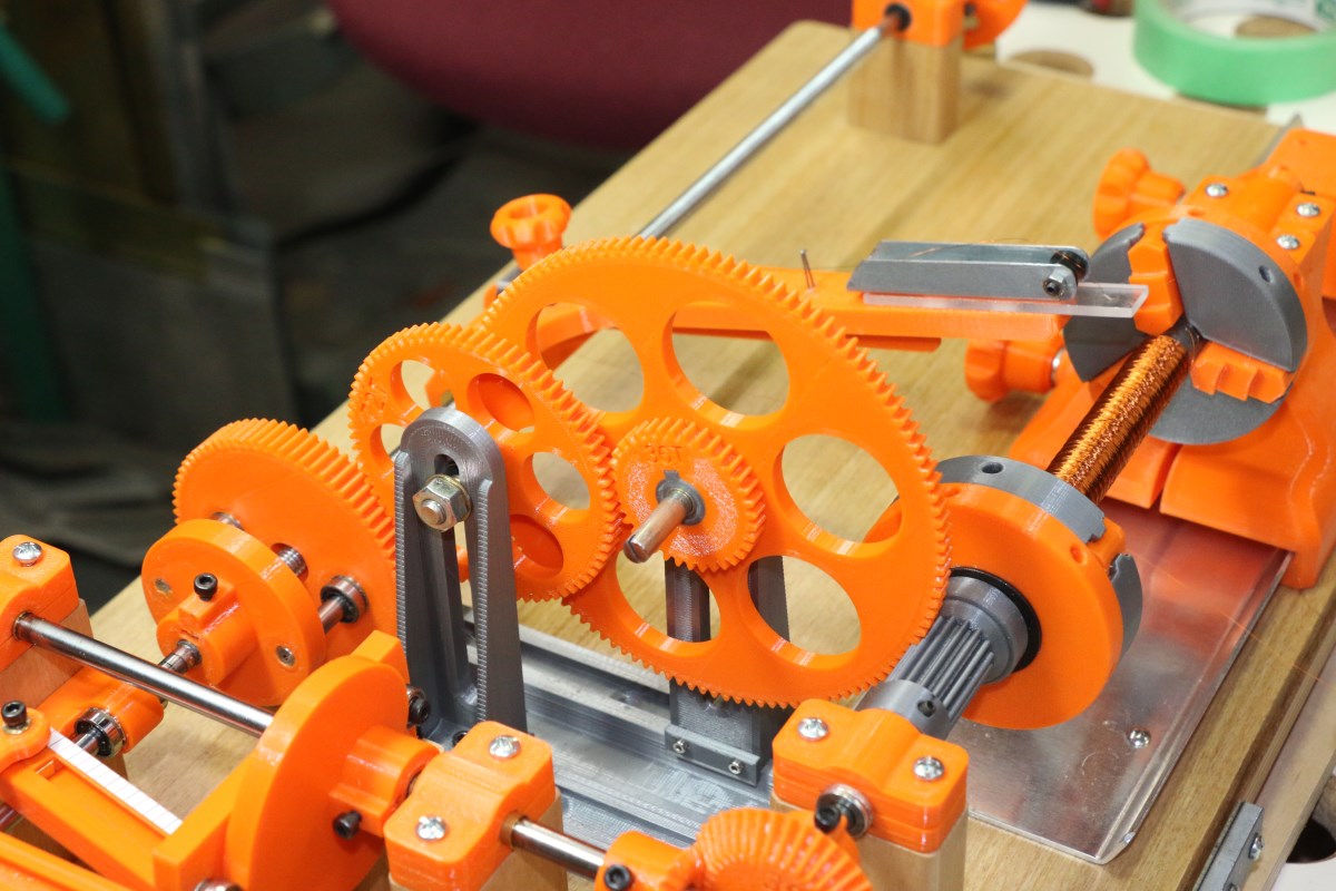
Continuing on down the main winding shaft we come to the bevel gears that both translate the motion by 90 degrees and provide an opportunity to select a gear ratio that rotates the chuck spindle at a slightly different rate from the cam shaft.
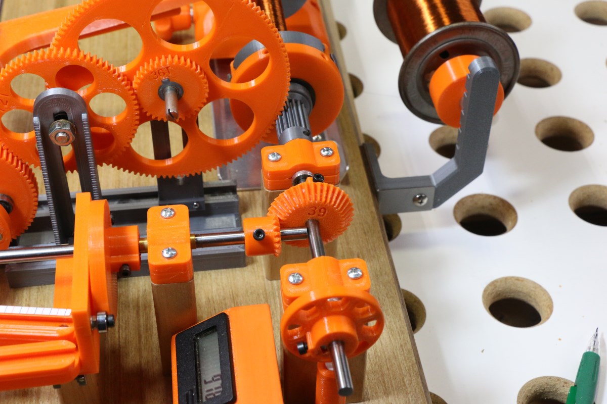
The ratio of the two bevel gears in the center of the picture has a huge effect on the appearance and the effectiveness of the universal winding.
The correct choice of ratio at the bevel gears ensures that new windings never land directly on top of lower windings, and it also affects how open or compact the winding will be. The ratio can also be changed more dramatically than the mild variations around 1:1 (39:40 is considered close to 1:1). For example, the small drive gear in this picture (20 teeth) with the larger 39 tooth driven gear gives a wind pattern of roughly two transverse feed-arm motions for every rotation of the spindle. This results in a greater crossing angle between winding layers with reduced capacitive coupling. The downside of this however is the problem that standard enamel-insulated wire is quite slippery and doesn’t like to stay in place with abrupt direction changes. Cotton- or nylon-served wire or enameled wire with a self-bonding coating is really needed for more extreme helix angles.
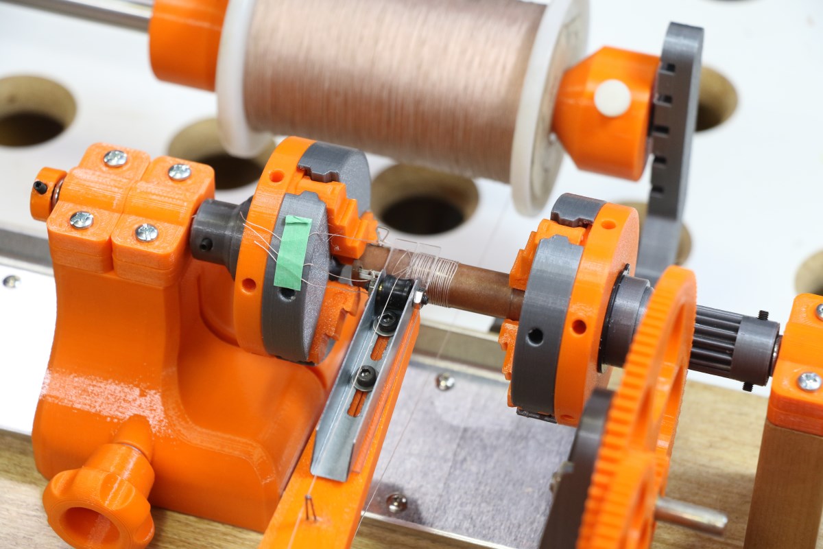
The foreground wheel at the end of the spindle shaft contains a single magnet to trigger the counter sensor. The long spur gear section in the gray hub of the drive chuck is part of the progressive gear train and will be discussed later.
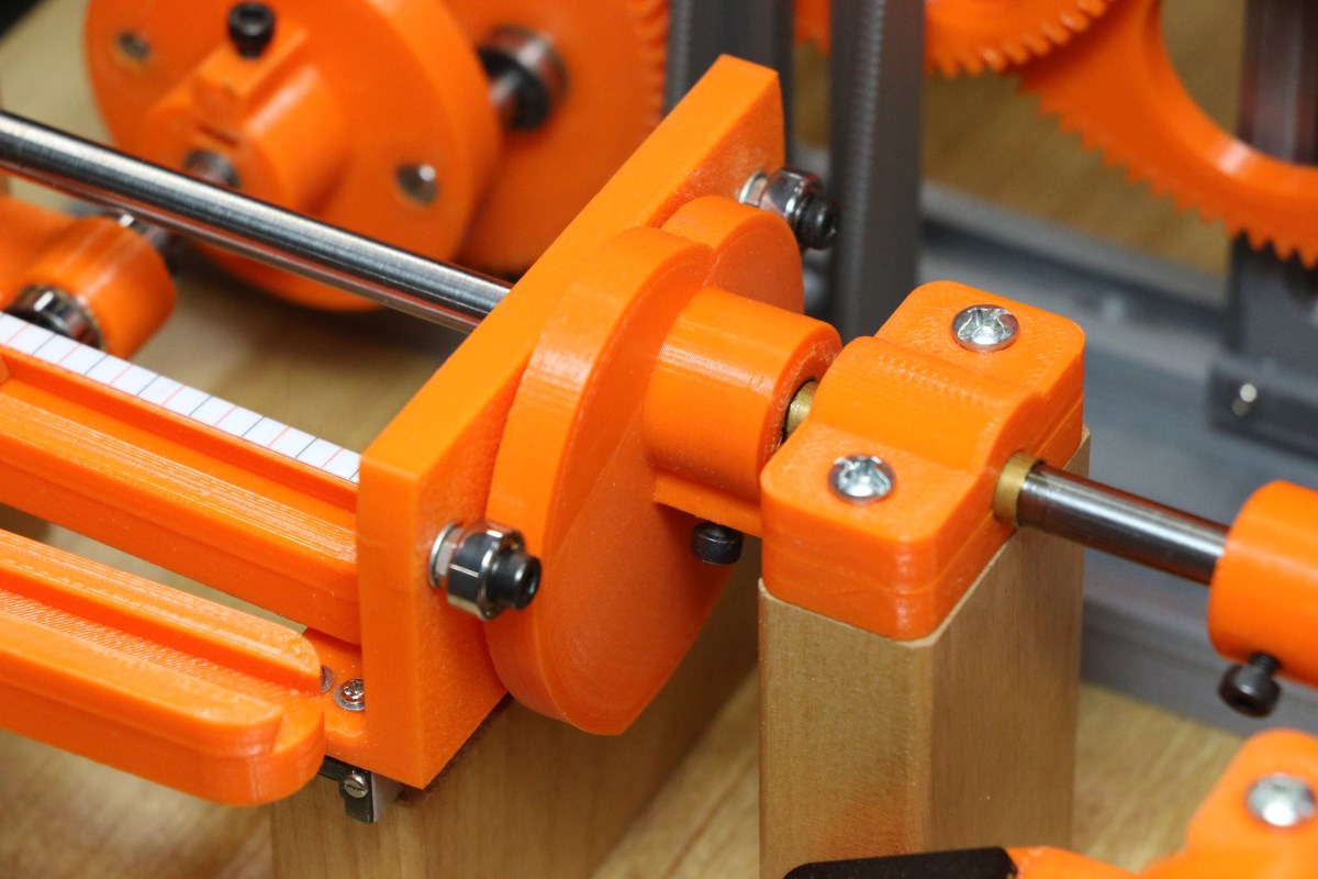
Backing up and looking at the lead screw shaft of the winder we see a 72 tooth gear that contains two linear ball bearings and a dog wheel with two pins that allows the gear to optionally rotate the lead screw (for progressive winds) while allowing free lateral movement for the universal winding motion. The lead-screw gear is coupled through a set of reduction gears driven directly from the spindle shaft, and in the picture below these are engaged to provide progressive feed (they are normally disengaged for universal winding only). This gear is itself restrained from lateral movement by a guide channel (the gray plastic part) mounted to the board. Please note that the center of this gear has a large clearance hole that allows the threaded lead-screw to pass through; only the gear rotation is coupled to the screw through the dog-wheel with the linear bearings.
The lead screw shaft is free to rotate and move laterally. The foreground gear can only rotate.
In the next several pictures we look at the wire feed arm that rests on the lead screw. This first picture shows a knob-adjustable wire tensioning pad, wire eyelets, and the semi-cylindrical heel piece that allows the wire to be fed from underneath the arm:
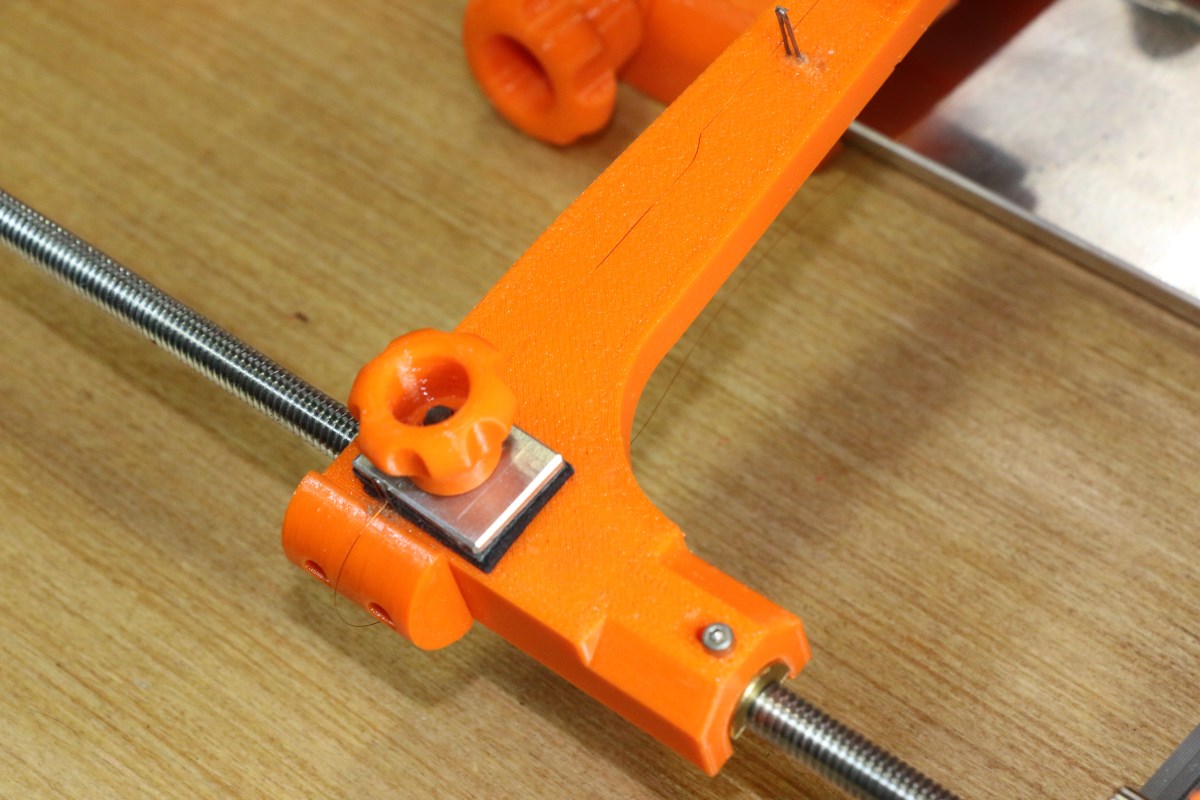
The pads under tension knob are leather. I need to improve on this because fine wire cuts a groove and the sandwich no longer grips it.
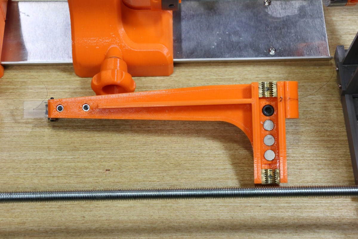
Once in a while an idea works out. The magnets and half-nuts allow the arm to be picked up and repositioned as needed without having to crank the lead screw.
The underside of the plastic arm has two threaded brass half-nuts and three magnets that allow the arm to be pulled off the lead screw and move to the approximate starting position on the coil core.
The feed end of the arm has a ball-bearing wheel that can be adjusted to be positioned directly above the precision wire guide that contacts the coil (see below). In this case that wire guide is a 0.125″ thick acrylic plate with a .010 hole drilled at an angle. If you look carefully you can see the angled hole as the short white line through the plate. This places the wire precisely where it needs to be and also provides a little squashing pressure on the winding as it is laid down. The metal bracket holding the bearing and the acrylic plate are both slotted at the screw holes to allow precise placement of the wire exit hole on the tangent point where the feed arm rests on the coil core.
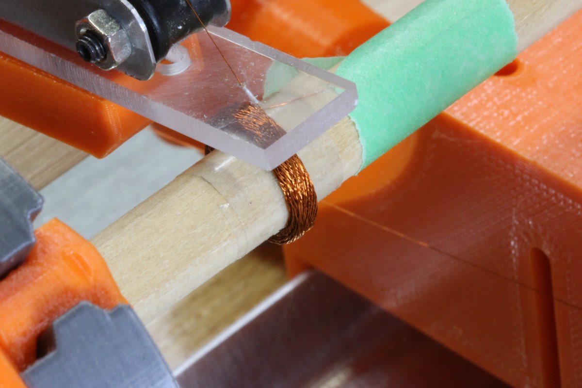
Winding a narrow “pi” coil section using #38 enameled magnet wire
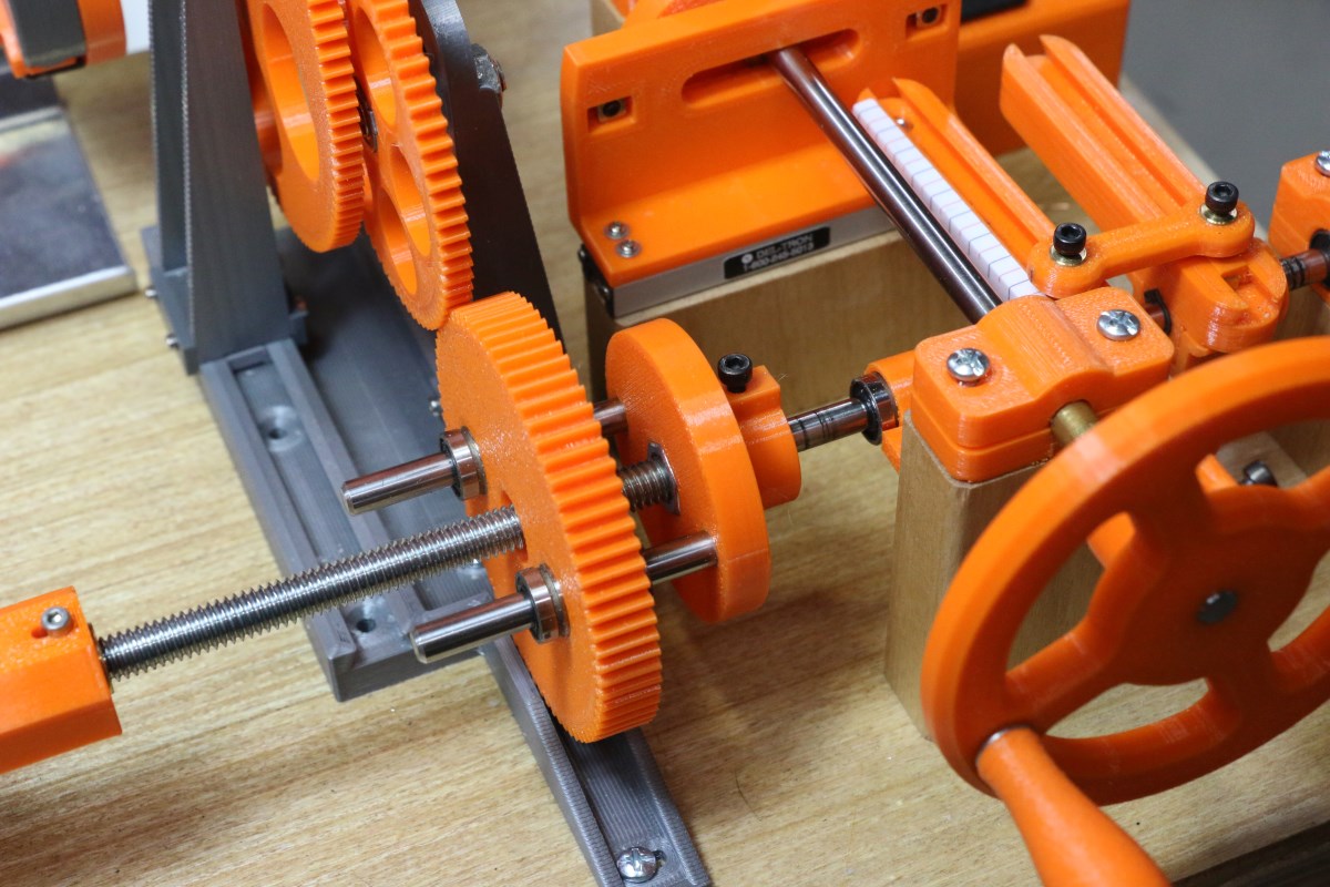
A “progressive/universal” winding pattern adds a slow lateral movement of the feed arm to the fast reciprocating motion that creates the familiar helical/honeycomb pattern. This is accomplished through the gear train shown below that engages with the pinion gear built into the hub of the drive chuck, reduces the speed, and slowly rotates the lead screw that walks the feed arm down the core. The gear reduction needed for the particular winding length is easily determined knowing that the lead screw (in my particular design) is 18 threads per inch, so it takes 18 turns to wind a coil length of one inch plus whatever the reciprocating motion for the universal pattern adds. The gear train shown below is made up of selectable gears keyed to shared hubs with sleeve bearings (one of which can be seen as the gray insert at the center of the large 120 tooth/36 tooth pair of gears):
The progressive gear train ratio shown here is (starting at the headstock chuck): 16:120 x 36:72, or 1:15. The 72 tooth gear in the 36:72 ratio is the lead screw gear, not the second to the last 72T gear which is simply an idler and doesn’t enter into the calculation. With 15 turns of the headstock required for 1 turn of the lead screw, and 18 turns of the lead screw per 1″ travel, this equates to 270 turns of the headstock for an inch of progressive movement. This was set up for a 1200 turn coil that would come out at about 4 1/2″ long.
Setting up a progressive gear train requires some jockeying of both the horizontal position of the vertical supports and the position of the gear shafts in the vertical slots of the supports. It looks more complicated than it actually is.
Above is another view of the progressive gear train. The vertical slotted arms that support the gears can be moved fore and aft in the dovetailed slots in the gray plastic base piece. The base piece is missing a bunch of screws because I haven’t decided if I want to keep the gear train or replace the entire section with a stepper motor and programmed arduino that counts the spindle rotations and steps the lead screw forward a number of steps. If I continue to use the progressive winder past my theremin project I should do this-it’s a lot easier than fussing with gears.
I have one piece serves no function (yet) that is shown below and in the very first picture of this article. I call it a midstock, and it’s simply a partial copy of the tailstock that if used would be positioned under the coil being wound and would provide some optional means of supporting a stationary guide or an adhesive applicator to bind the coil as it’s wound. I don’t have any ideas for this yet, but I left four threaded holes on top for when I do.
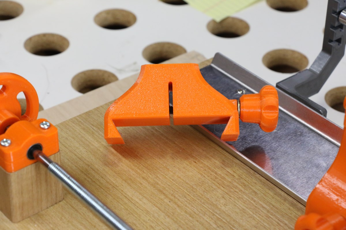
A little crude, but it works: the vertical slot allows the whole piece to compress when the knob is tightened, clamping the dovetail tightly to the aluminum bed.
A couple more things that have been visible in previous pictures but that I haven’t mentioned…
The aluminum plate under the chucks started off as simply a tray to catch spills when the coils are coated with shellac or q-dope while still in place. But at the same time I needed something to guide the tailstock and provide a means of securing it, so I bent two 60 degree flanges in the .0625 aluminum and designed the tailstock with a matching dovetail.
The tailstock by the way has a free wheeling sleeve bearing and the second chuck provides a versatile secondary support for the other end of the core.
And finally, the wire spool support is shown below. This is made of a piece of 1/2″ O.D. aluminum tube with two printed cones that adjust to grip the wire spool. The ends have 1/8″ protruding pins that allow it to rotate in one of the five pairs of slots in the gray arms. You can’t have a spool of fine wire flopping around on an undersized shaft; it must be allowed to rotate smoothly or the wire will break. I really should add just a little bit of friction to shaft rotation. As it is I have to provide a little wire tension by feeding it through my fingers.
I was lucky enough to find this surplus spool of #36 cotton covered wire from a surplus store. This is relatively easy to wind compared to enameled wire because the windings tend to hold together better.
That pretty much wraps up the discussion of the coil winder mechanics. Although it is entertaining to watch in action, I’d be the first to admit that a stepper motor and Arduino solution would possibly be a more practical solution. I just love gears and cams and mechanisms that look a little Rube Golberg-y, and I think this meets that criterion.
What I Have Learned About Coil Winding (And What I Don’t Know)
- What they say is true – you can’t wind normal magnet wire into those nice crisp narrow pi sections like you see on some commercial RF inductors. I’ve only been able to do that once with #38 wire that has virtually no springiness. Some have had luck with winding a thread along with the wire, but it hasn’t worked for me. Self-bonding magnet wire only appears to be available directly through distributors, and I don’t shop that way. Plus self-bonding wire needs some sort of activation either by solvent or heat or whatever to make it sticky, and it’s just not something that seems practical. I would love to find some DIY information on this, but I haven’t yet.
- The wire feeder needs to place the wire onto the core without allowing it to wander on its own. A wire loop or eyelet feeding wire that has space between the wire exit and the core contact point doesn’t work well because the wire will just go wherever the underlying layer of wire pulls it.
- If ferrite cores are used the dielectric constant and the resistivity of the ferrite should be considered. High relative-dielectric ferrite will cause increased capacitance between windings, leading to lowered SRF. Low resistivity of the core material will also increase inter-winding capacitance.
- The bevel gear ratio has a large effect on the number of turns that can be packed into a given volume. The 39:40 ratio with small cores can give the very compact winding where each new turn of wire is placed directly adjacent to the previous one. Higher ratios such as 39:44 will place each new turn a considerable distance from the previous one, resulting in very open cores with lots of air spaces.
- Visualizing winding patterns is difficult without a 3D graphing math program. An oscilloscope and a dual-output signal generator can be set up to give some idea of how a particular gear ratio will affect a winding. The scope is set up in x-y mode so that you are able to display a Lissajous figure. A sine wave of frequency f is fed to the y-axis, and a triangular wave of frequency (f * bevel gear ratio) is fed to the x-axis. The y-axis scaling will affect the apparent diameter of the “winding”, and the x-axis scaling will adjust the width. The resultant Lissajous figure that emerges gives some insight into how a particular winding pattern will appear.
- The introduction of progressive movement into a universal winding can result in unexpected patterns. Sometimes you’ll see a certain banding that you think is related to the cam width setting, but it will completely change or disappear when this parameter is varied slightly. Like Lissajous figures mentioned above, where changing the frequency ratio between axes (which is equivalent to changing the bevel gear ratio) will make recognizable patterns emerge at very specific ratios, wire winding patterns will look pretty and organized if you hit the right ratios. The rest of the time a perfectly functional universal/progressive wind may just look like scramble winding done by hand.
- Because the helix angle is a function of the core diameter as well as the feed-arm stroke and the bevel gear ratio, small cores can only be wound in narrow sections unless cotton or self-bonding wire is used. Larger cores can get proportionally wider windings before they reach that 15 degree (or whatever) critical helix angle where the windings start collapsing.
- I am still seeking a solution that will provide a means of supporting narrow pi coil sections as they are winding and until they can be bonded with q-dope or some other fast-drying binder. I have 3D printed multi-section bobbin cores with separators that keep the windings from collapsing, but I would like to be able to replicate those nice self-supporting multi-section pi wound inductors without having to use hard-to-find cotton-served wire.