Servicing Your Atlas AZ-EQG Equatorial Telescope Mount
Disassembly, Tweaking, and Tuning
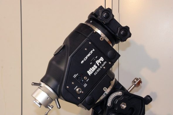
The Atlas AZ-EQG mount is a popular and affordable dual-mode ALT/AZ and equatorial go-to mount manufactured in China for the Taiwanese company Synta and distributed in the US by Orion Telescopes and Binoculars. A nearly identical model (in white instead of black) is distributed (outside the US, for now) under the SkyWatcher name and goes by the AZ-EQ6 model number. Another Synta model that is even more popular in the US is the Atlas EQG, an equatorial-only model that is also sold in the US and worldwide as the Skywatcher EQ6.
The wider popularity of the basic EQG and EQ6 models has resulted in a good amount of user information being shared in the astronomy community, including some well documented disassembly and tuning procedures. The information on the AZ models is a little less plentiful, so I thought it would be helpful to document some of the steps that I went through while cleaning, lubricating, and tuning my mount recently.
While the basic and the AZ- mounts have many similarities in size and weight capacity, they are quite different in their construction and the disassembly procedures for one model aren’t particularly helpful for the other. In searching through the forums I was able to find some disassembly pictures and information that was helpful to get me started, and I hopefully I can add some additional photos and insight of my own.
WARNING: This article is intended to be more of a chronicle of my adventures and findings than it is a tutorial. I do not recommend that you disassemble your mount unless you have a compelling need to do so and have the basic skills and common sense to know when to use a hammer (hint: not here) and when to use a feather touch. Legitimate reasons for digging into your out-of-warranty mount can include binding, slipping clutches, tracking problems indicative of debris on the worm, or balky encoders. In my case, it was all of the above. But be warned, the worm and worm wheel are precise pieces and a bump only a few millionths of an inch high or a scratch on a worm tooth can show up as an significant error in the scope, so be careful!
In my disassembly of the mount I did not run into any items that required undue force to remove. If you are one of those choosing to remove and upgrade any press-in bearings you may run into those problems, but I found everything else to come apart in a very predictable manner. An extra hand would have helpful at times, but is not necessary.
I would have found the disassembly easier to accomplish if I had performed most of it with the mount still on the tripod, but in the interest getting photos under good light I moved over to a table. In the end I found some foam blocks to help cradle the curved parts that wouldn’t stand up on their own.
Disassembly of the Declination (DEC) Axis
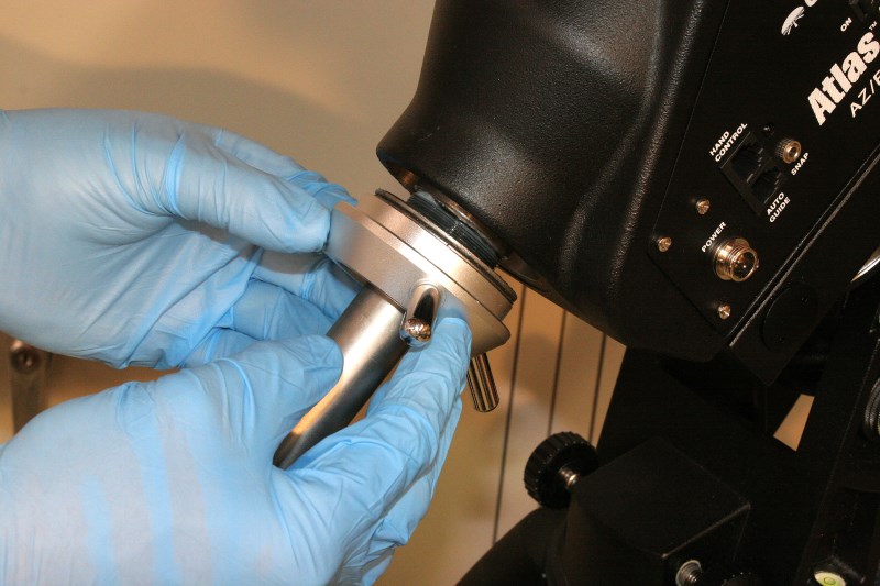
Begin by loosening three set screws spaced equally around the collar located on the counterweight shaft just below the captain’s wheel. The lever that secures the retractable counterweight shaft is loosened and the shaft is allowed to slide to full length. The collar should unscrew easily – in my case no tools were needed.
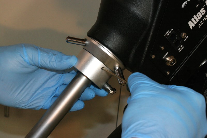
Loosen the three set screws that lock the end collar
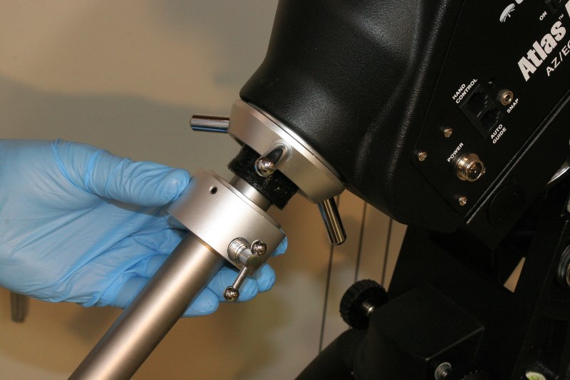
Unscrew collar from end of DEC spindle
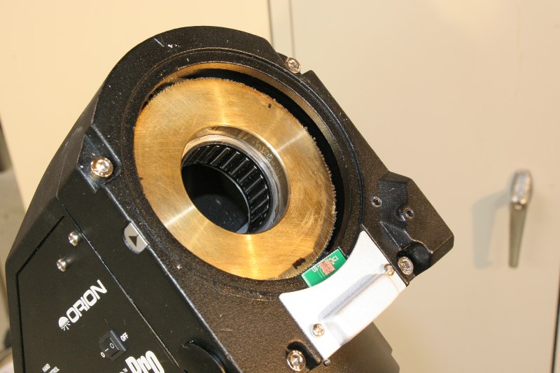
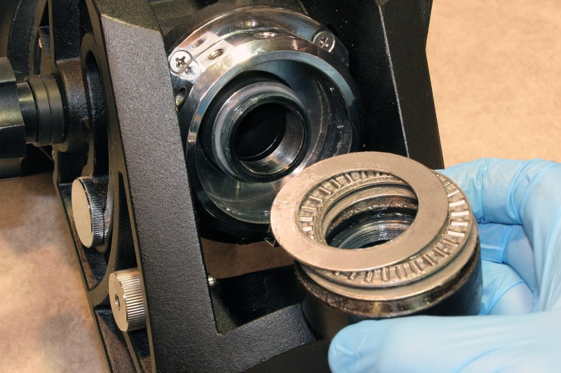
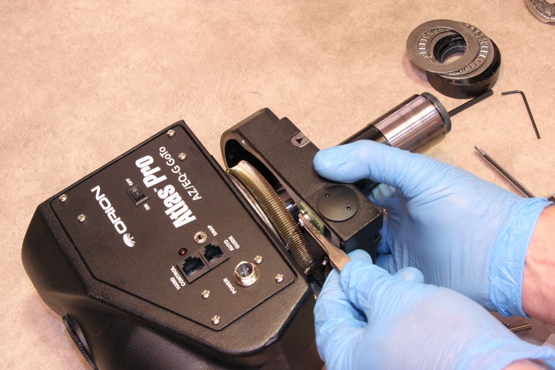
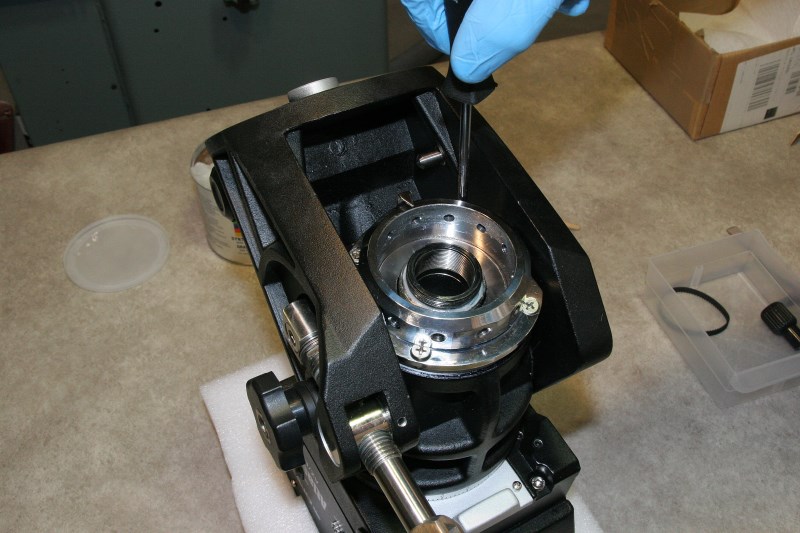
With the collar removed the captain’s wheel is then unscrewed from the end of the declination axis spindle. Before removing it completely note that there are three thrust bearing parts that need to be caught. If any or all of the parts stick in the end of the housing they may need to be coaxed out with curved tweezers or a magnet.
The arrangement of thrust bearing parts shown here will been seen many more times ahead and the order is always the same: thrust ring, bearing race, and thrust ring. The rings are not ordinary washers or shims – they are hardened steel surfaces on which the roller bearings ride, and just for fun I polished mine a bit on a buffing wheel. The rollers of the bearing cages should never be in contact with aluminum or brass or anything other than these hardened rings.
Remove Captains Wheel and Lower Thrust Bearings (Bearing Stack May Stick in Housing)
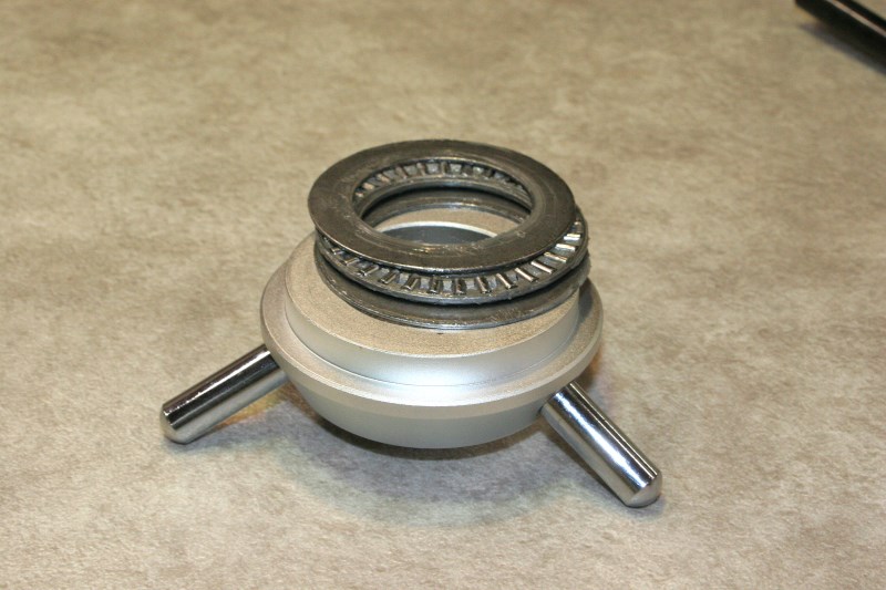
DEC Clutch Lock Thrust Bearing
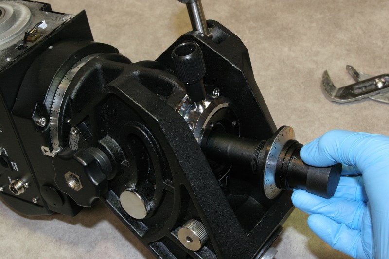
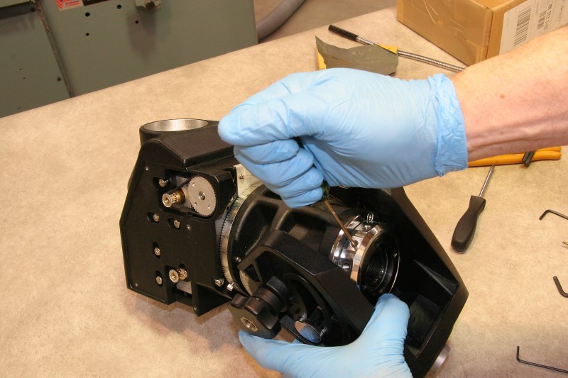
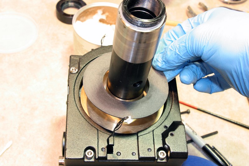
At this time the declination spindle is free to be removed, but read on – this needs to be done carefully. This is the point at which having the mount on a tripod helps. The RA axis should be locked with the counterweight shaft near vertical while removing the DEC shaft.
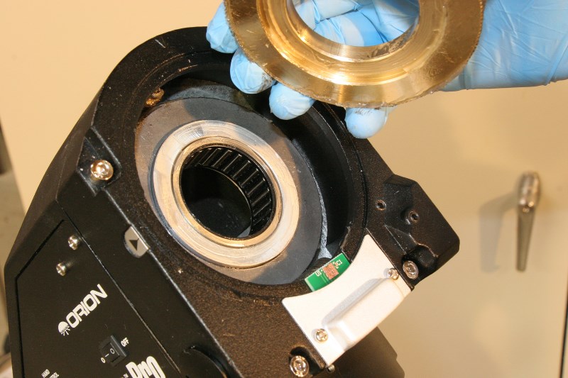
WARNING: Always take care when working around the brass worm wheel and take measures to make sure that it does not stick to the DEC spindle and drop as it is being lifted out. The worm wheel should stay in the housing, but you may need to help it stay there.
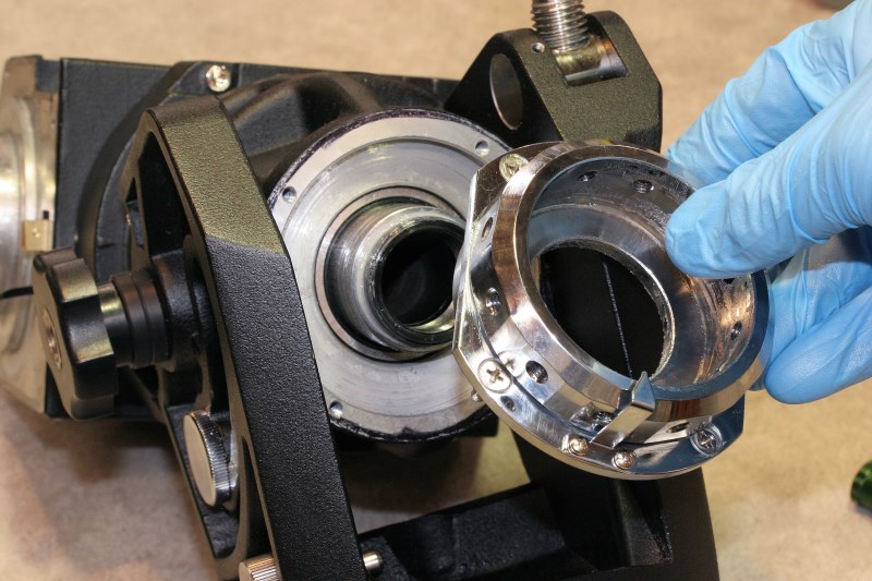
ANOTHER WARNING: Pulling the DEC shaft will expose the DEC encoder optical wheel – actually a ring – on the underside of the puck hub and DEC setting circle. Avoid touching this and certainly do not use any prying tools to lift in this area.
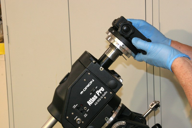
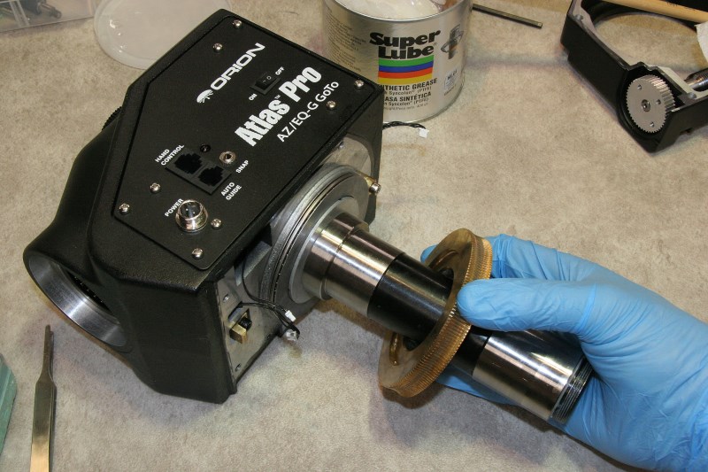
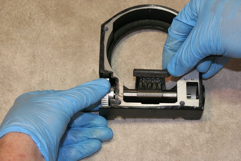
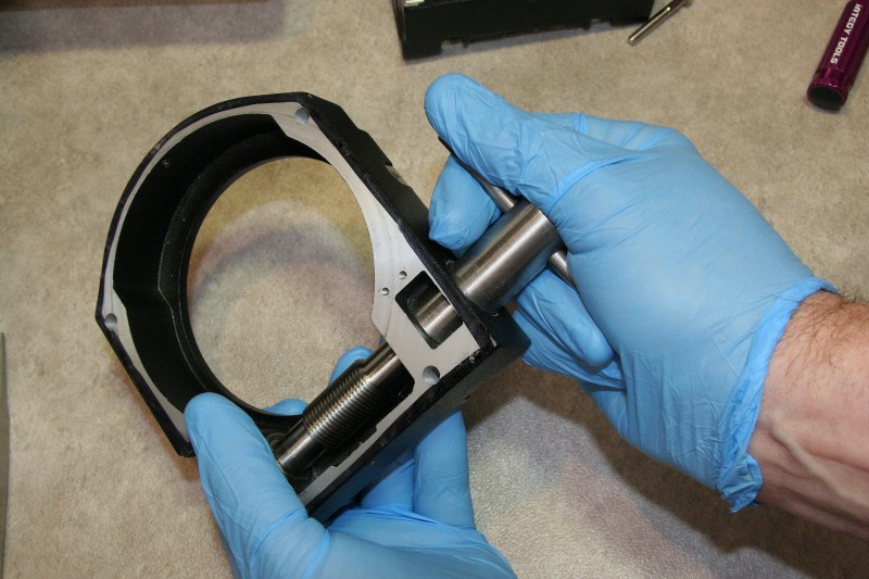
Take care to hold the declination shaft straight on-axis as you lift it free of the bearings
The declination spindle is actually a hollow tube that provides space into which the counterweight shaft can be retracted. The spindle rotates on two slightly raised precision-machined (albeit a little undersized, IMO) journals that mate with roller bearings which are pressed in the housing. As the spindle is pulled out it will loosen a little as the journals first slide out of their respective roller bearings, but the lower journal will have to be carefully aligned on-axis in order pass through the upper roller bearing and slide out the last inch or so. Nothing should be forced – if the spindle doesn’t easily slide out and feels stuck, try different alignments until you hit the spot.
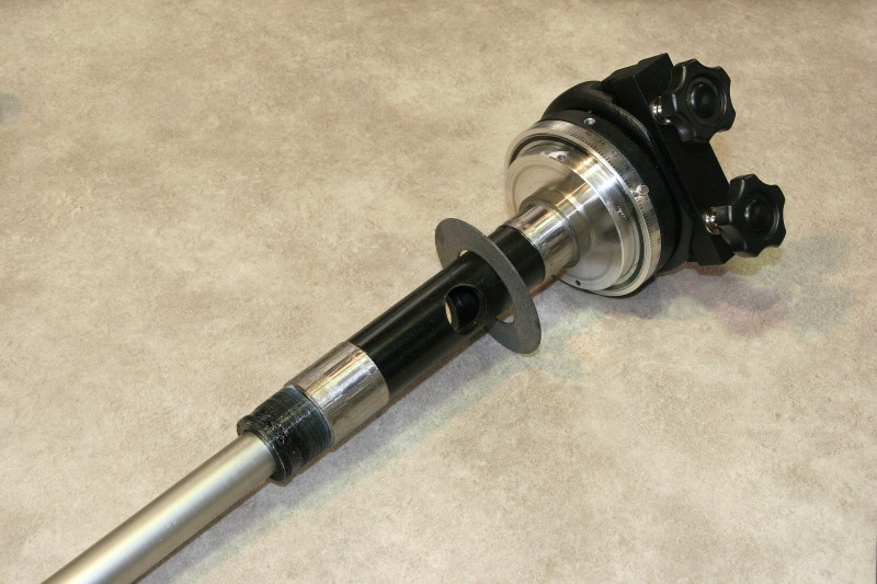
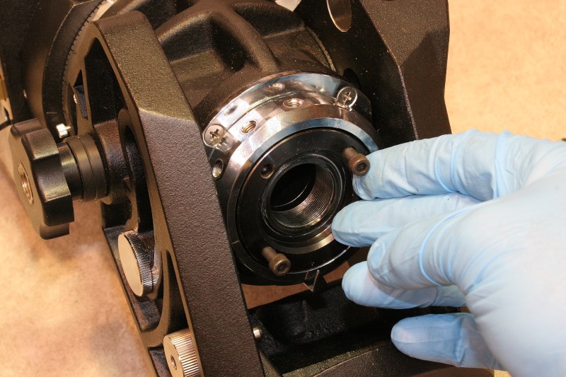
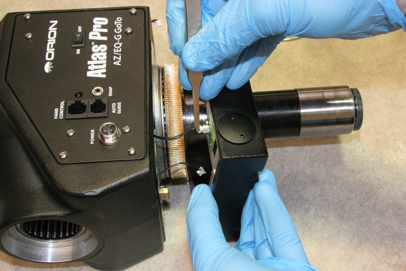
The fiber ring is the declination clutch. Keep it free of grease at all times!
The large ring seen in the above picture is actually the DEC axis clutch pad, and it is prudent to handle this with care so that it stays as free of grease as possible. It will be cleaned later, but handle it so that it doesn’t pick up grease from other parts or your hands.
If your DEC worm wheel clears the worm housing it can now be removed and set aside for safekeeping. If it doesn’t quite clear, remove the four stainless socket head screws holding the worm housing casting in place and remove it, and then remove the worm gear. The worm wheels are greasy and slippery, and dropping them will ruin your day and probably more!
DEC Worm Wheel
Worm May Lift Out; If Not, Remove Housing First
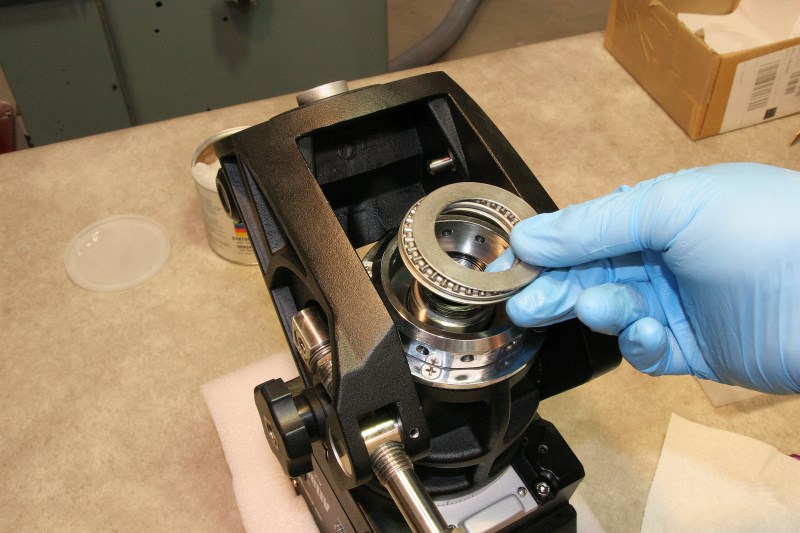
Under the worm wheel you will find another three-part thrust bearing stack. Again, the last ring will probably stick in the housing – don’t forget to remove it.
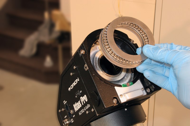
DEC Upper Thrust Bearing
DEC Worm Wheel and Upper Thrust Bearing
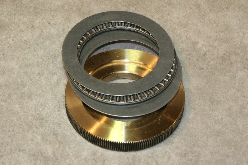
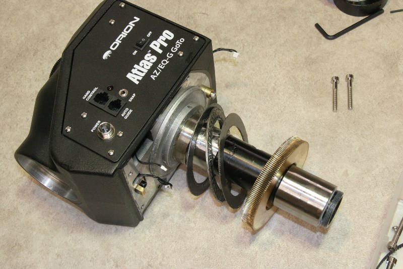
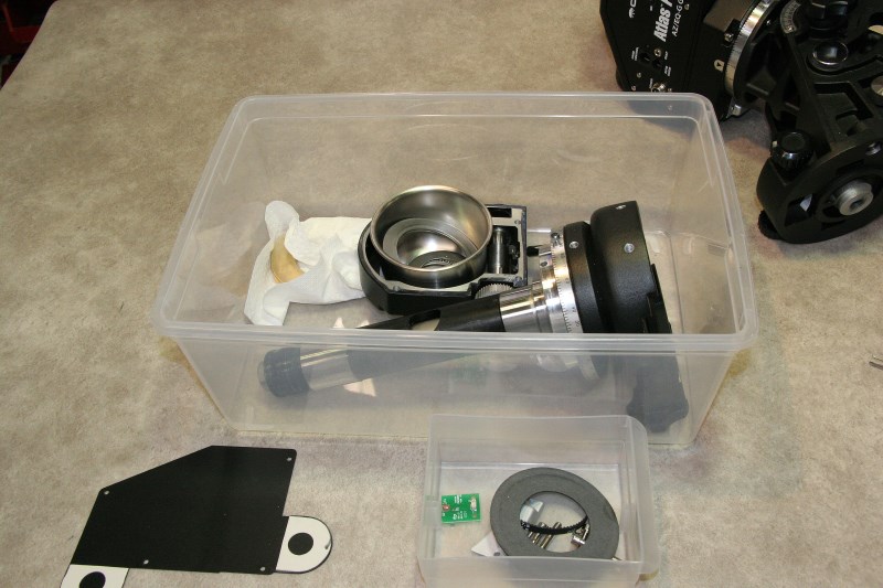
And here is the order of all the parts removed thus far, before cleaning:
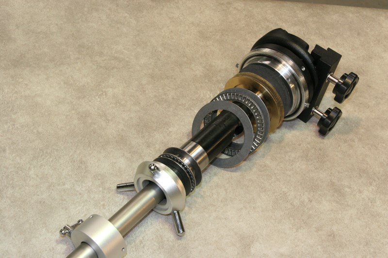
From the Bottom: End Collar, Captains Wheel, Lower & Upper Thrust Bearings, Worm Wheel, Clutch Disk, Puck Casting
I had not planned to perform any bearing upgrades unless I found something that forced the issue. Happily I did not run into any bearings that appeared to be rough or damaged. The large cylindrical (not tapered) roller bearings for both axes did have some perceptible radial play that was less than ideal, but I felt that this was more of a design shortcoming that would not necessarily go away even with very expensive replacements.
Although I chose to keep the stock bearings, one of the things I did want to do was try to decrease the heavy drag that was present on both axes ever since the mount was new. Balancing both axes was difficult because of the rotational stiffness even with clutches disengaged, and this had always felt like it was caused at least partially by grease drag.
This turned out to be true. All of the bearings were well packed with grease – to excess. Every roller in the bearings had to plow through a wall of grease, and this is unnecessary. It was my feeling that most of this should be removed while still leaving an adequate coating on every rolling or sliding surface.
As an example of how too much grease can create drag, I once installed some new heavily grease-packed high-RPM bearings on the spindle of a milling machine. For nearly the first hour of operation the motor current was so excessive (from grease drag) that it would trip the overcurrent protection, and I had to slowly work up to speed until the bearing grease was redistributed out of the way of the balls.

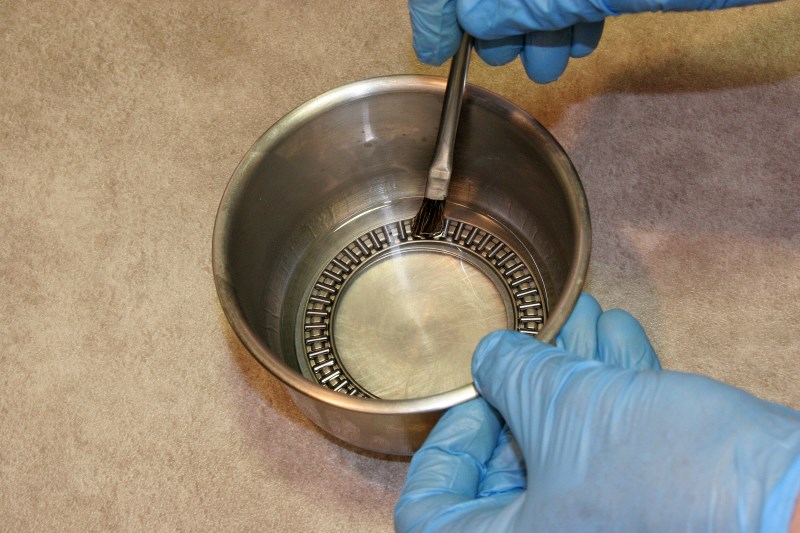
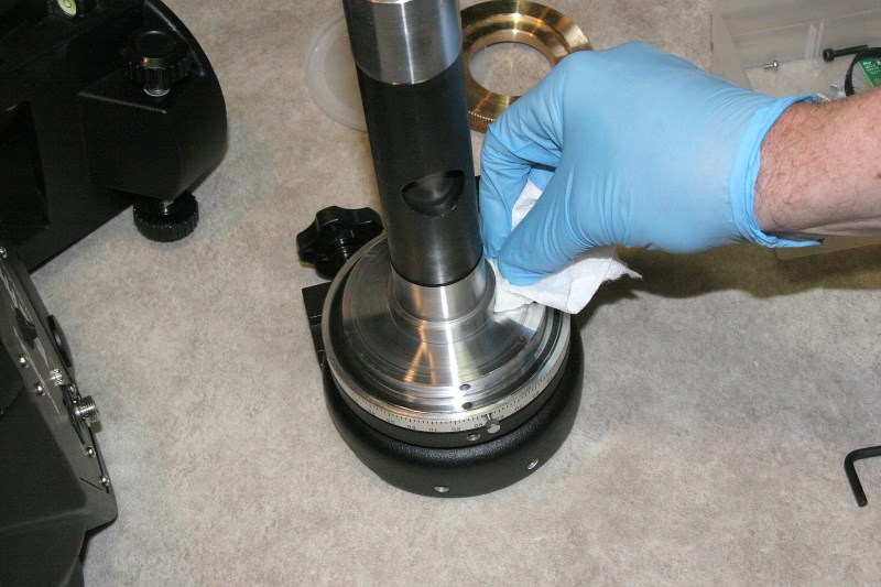
Clean Grease From Spindle Roller Bearings
Back to the telescope mount… Since I didn’t want to remove the roller bearings from the housing to wash and re-grease them, I simply wrapped a paper towel around my finger and “orbited” the roller bearings like a planetary gear, picking up excess grease. After repeating this several times with a clean wrap of paper towel, the rollers could be heard rattling in their cages, and this was a sign they were getting clean. I did this for all of the roller bearings that would not be removed for cleaning. They would later be re-greased, but with a controlled amount.
The AZ-EQx models come equipped with optical rotary position encoders (low resolution), unlike the basic EQx equatorial mounts that derive position information entirely by counting clock pulses to the stepper motors (hoping you don’t de-clutch or bind up and skip steps along the way). For this disassembly these encoders need to be at least unplugged and preferably removed in order to remove the worm housing.
The DEC encoder cover is removed, and the encoder connector is unplugged.
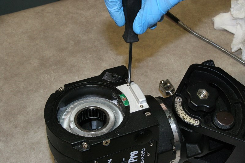
Remove DEC Encoder Cover
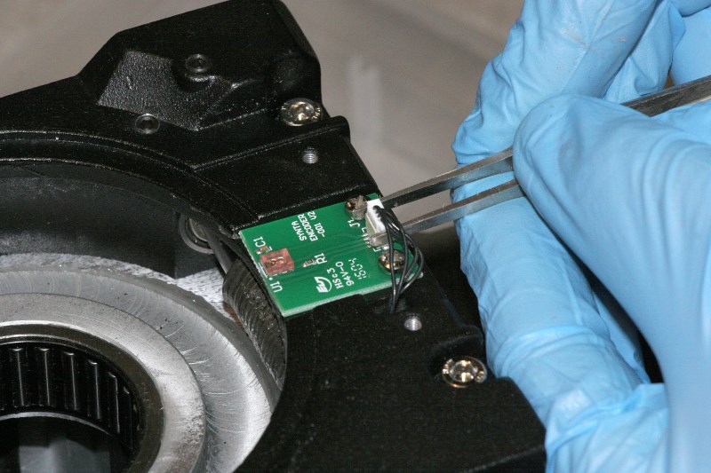
Pull Wire Connector From Encoder Board
Remove the encoder board and set it aside to prevent anything from damaging the tiny lenses on the encoder module. Push the encoder lead through the rectangular hole in the worm housing.
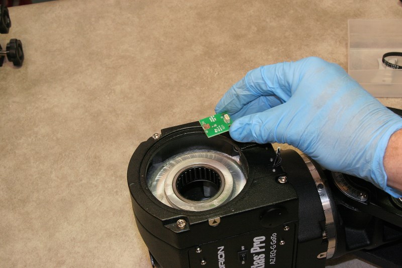
Remove DEC Encoder Board
Push Encoder Wire Through Hole in Worm Housing
In preparation for removal of the DEC worm housing it is necessary to remove the drive belt that couples the stepper motor to the worm shaft. The cover is removed from the drive side of the housing, and the three socket head screws that hold the stepper motor are loosened sufficiently to allow the motor to move and relieve the belt tension. There appears to be an allen screw that pushes on the motor to set the belt tension, but I was unable to turn mine very far so I just carefully coaxed the belt up the side of the larger flangeless sprocket until the belt came off.
If you wish you can remove the belt for the right ascension drive now as well.
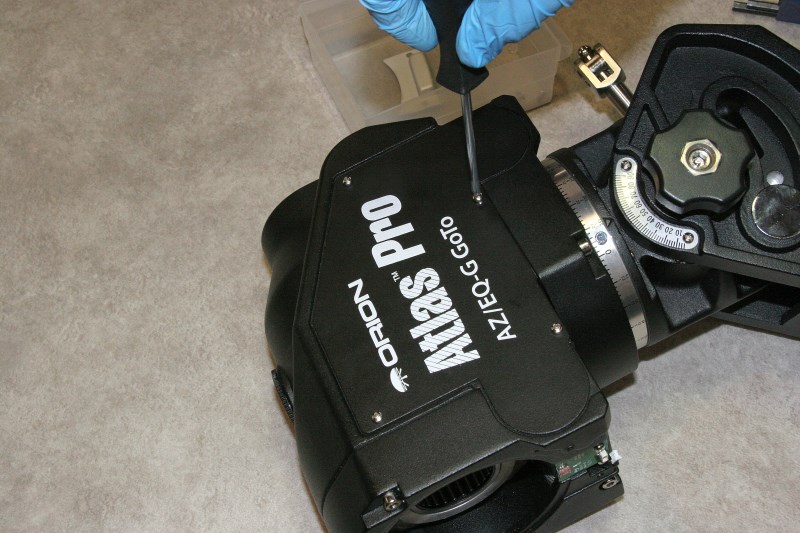
Remove Side Cover to Expose Drive Belts
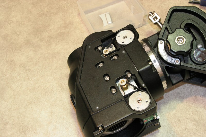
Upper Belt for is for RA, Lower is for DEC Axis
Loosen Screws to Release Belt Tension – This Allows the Stepper Motors to Move
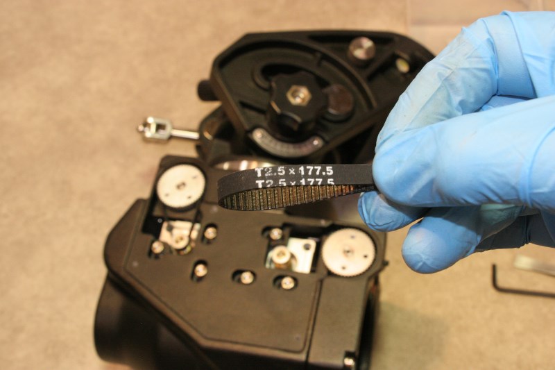
DEC and RA Belts Are Identical
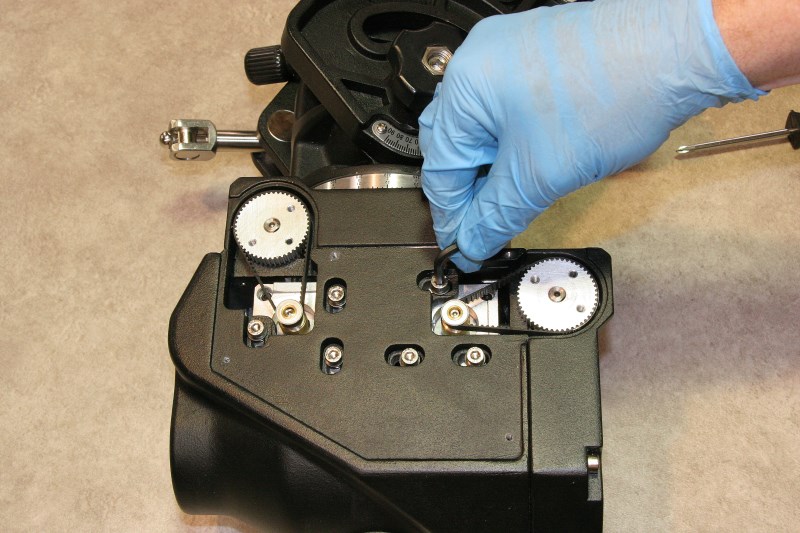
Next loosen one or both of the worm-mesh adjustment allen screws on the ends of the worm housing, and then remove the four stainless socket head machine screws.
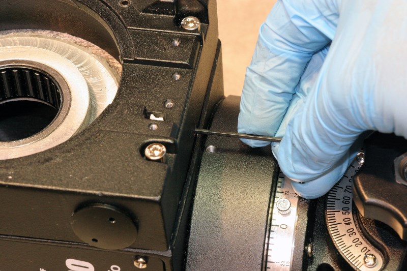
Loosen Worm Gear Backlash Set Screw
DEC Worm Housing Removed
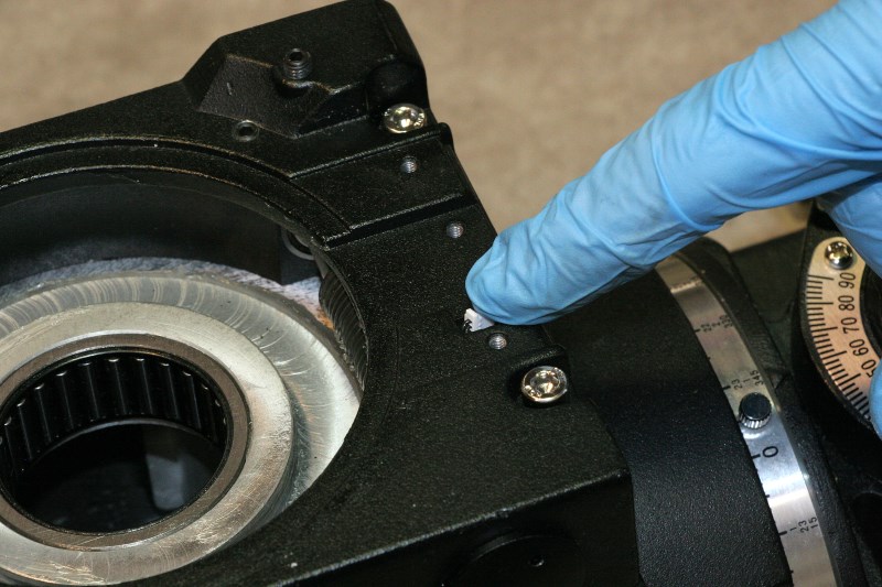
In forum searches I have come across a few stories of people finding foreign objects inside their mounts – sometimes metal chips and swarf from machining operations, and once even a staple.
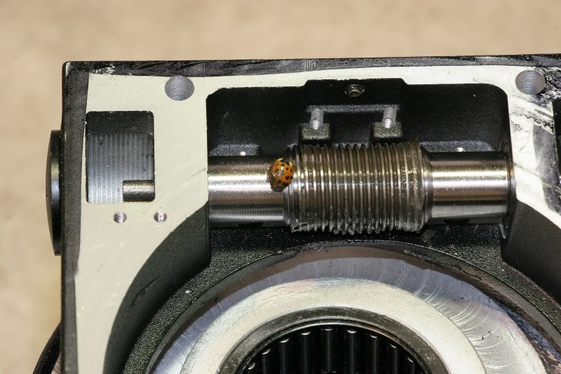
My stray inclusion was this little guy who was buried in the heavy grease under the worm.
Disassembly of the Right Ascension (RA) Axis
Remove the polar scope by unscrewing it. If you have trouble gripping it, don’t go for the channel locks. Try wrapping a few turns of friction tape around the scope to give a better hand grip.
Remove the Polar Scope and Set it Aside.
Surrounding the polar scope hole you will see a black threaded collar with four holes that are used for removal with a pin-style spanner wrench. This collar is threaded on the end of the RA shaft and then secured with three allen set screws equally spaced around the circumference. The set screws are not visible and are only accessible through the handle holes in the large faceted chrome clutch ring.
With the RA clutch unlocked, stick an allen wrench through any threaded handle hole and rotate the RA body assembly until you find the first set screw hole. Loosen the set screw (but not too far). Rotate the RA shaft about 120 degrees and you will find another hole with a set screw. Loosen it, and repeat until all three set screws are loosened.
Three Set Screws are Accessed Through Chrome Ring
The black collar may be unscrewed if you have a proper spanner wrench, or if you don’t, use some other tool that won’t make a mess of things. I usually use some close-fitting socket screws in the spanner holes with a block of wood between them for leverage – the threads on the screws help keep them from falling out of the holes. In this case I just grabbed the screws and turned the whole collar by hand. If you feel like you are catching on something as the collar unscrews, recheck the set screws to make sure that they are not galling your threads or out so far that they are getting caught in the holes in the chrome clutch ring.
If You Don’t Have a Spanner Wrench, Improvise
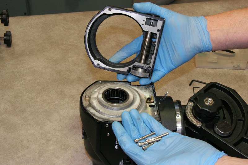
Once the black collar is removed you can remove the little chrome pointer and unscrew the chrome ring. This is a very fine thread, so give it some time. Once the ring is removed, the four flat head screws can be reached to allow removal of the mating chrome flange.
Collar and Lower Thrust Bearings Are Removed
Right Ascension Clutch Lock (Shown Reassembled After Disassembly For Removal)
Once the clutch lock parts are removed you will now be staring at a familiar stack of thrust bearing parts. Pull all three parts out.
If you are now still working with the mount on a tripod, I would recommend that you remove it and go to the bench. If you try to lift the RA axis up from the mount base you will run the risk of having the RA worm wheel fall and damage itself. A piece of thick foam with a rectangular hole cut through it will act as a nice soft vise to hold the housing with the RA spindle pointing up.
Lift the mount’s base castings either up or sideways off the RA shaft, while making sure the RA worm wheel stays safely in place against the worm. Again, alignment matters when slipping the spindle through the bearings, and this is where you may find some extra hands to be helpful.
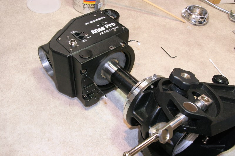
RA Axis Spindle Pulled From Base
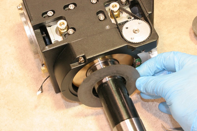
RA Clutch Disk
Once separated, set the base casting aside and concentrate on the body and the RA spindle. Remove the clutch disk, keeping it free of grease as before.
I did not try to remove the brass RA worm wheel this time until after I removed the worm housing. The encoder cover, wire, and encoder board removal are the same as for the DEC axis.
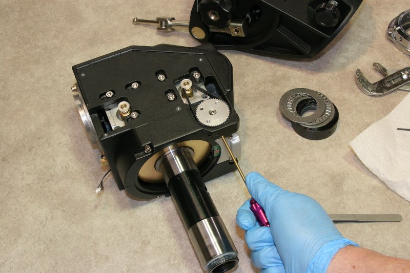
Removing RA Encoder Cover
Again loosen the worm backlash adjustment set screws and remove the four stainless socket head screws. However this time you have to lift the worm housing up just far enough to allow removal of a new wire that plugs into another little board at the cover-end of the worm shaft. This is for an index wheel that detects the worm position every revolution. Unplug this wire and the RA worm housing is now free.
RA Worm Has an Extra Encoder Wire – This is a Worm Index That Gives One Pulse Per Revolution
RA Upper Thrust Bearing and Worm Wheel
Now you are free to remove the brass RA worm wheel and the thrust bearing stack under it. This is how the parts are ordered:
Cleaning
Warning: If you use lacquer thinner or alcohol as cleaning solvents make sure that you stay away from sources of ignition.
If you wish to clean excess or old grease from all four of the axis roller bearings as described earlier, do so now.
I used lacquer thinner and a plastic-bristle brush for cleaning the thick grease on the thrust bearings and the worm wheels. As the cleaning progresses, use new solvent and dispose of the grease-laden material. Some have described using water-based cleaning, but you will probably have a much harder time cleaning up all the crevices in the worms and bearing cages. However, if that works for you, make absolutely sure that you dry everything thoroughly or blow the water out before re-assembly.
Use particular care in cleaning the teeth of the worm and worm wheel. Don’t use a wire brush. Remember, a few millionths of an inch or even scratches on the tooth of a small-diameter worm gear can translate to arc-seconds of error.
Degreasing Thrust Bearing Cage
Removing Worm Grease w/Plastic Brush
Cleaned DEC Axis Parts Set Aside
When all of individual components are clean the RA and DEC shafts and any parts of the base or housing castings that are slathered in grease can be cleaned up with a rag or paper towel and a little lacquer thinner. Avoid the black (or white) paint or powder coat – the solvent may take it off.
Lubrication
The bearings may be re-greased sparingly after they are all cleaned. Use your own judgment here, depending on your goals. One of my goals was to reduce the drag on each axis for balancing purposes, so I chose to stay light on the grease.
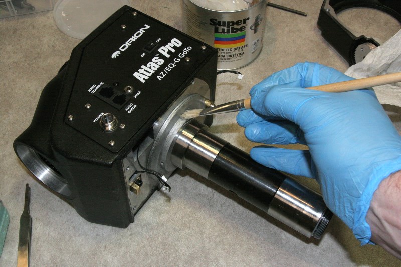
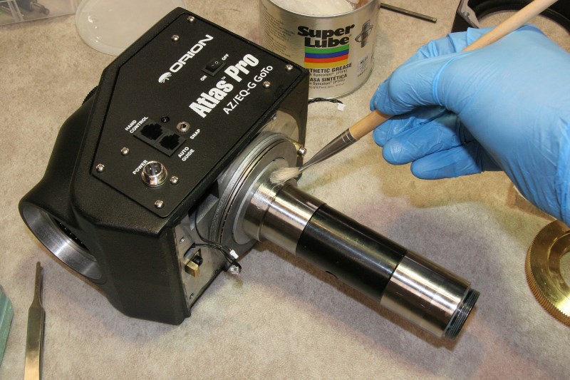
Just prior to re-lubricating the parts it is helpful to blow high pressure compressed air into the worm teeth and the bearing cages to clean out any remnant grease or brush bristles. Wear eye protection.
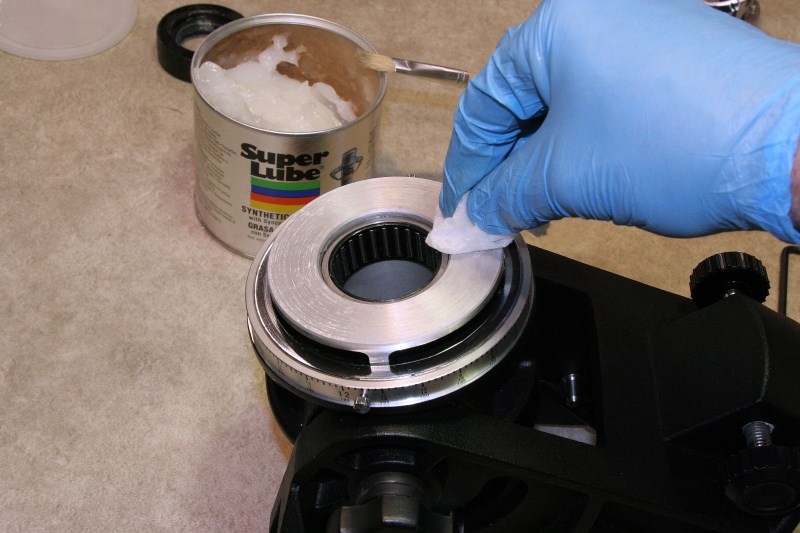
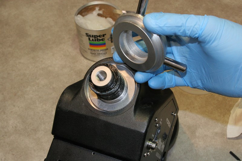
For the bearings and the worms, I used Super Lube synthetic grease. The thrust bearing cages were spread with about a pea-sized dab, worked around all of the rollers thoroughly. The thinnest layer possible was spread on the working face (the roller bearing side) of each of the thrust bearing rings, but the back sides that contact the aluminum castings or the brass worm wheels must be left free of grease (you DO NOT want them to slide at those interfaces).
After all the old grease was removed previously from the four large spindle roller bearings, a couple pea-sized dabs of Super Lube were redistributed on the rollers of each bearing using the same “planetary finger” method used to clean them. The journals on the DEC and RA spindles were covered with a very thin protective layer only. The bearings are already greased and too much extra here will just get squeezed toward the clutch and worm wheel.
The worm wheels and worms can be greased effectively with a fairly stiff bristle brush, but make sure that it is clean and doesn’t shed bristles ( you want the grease on the worm gears to be clean-room clean, almost). A toothbrush works. The only grease that matters is that where the worm contacts the brass worm wheel, so you can apply grease sparingly into the crevices of the teeth. If you blob it on you will run the risk of the excess working into your clutch. I was actually fairly generous in this area, but I did favor application on the edge of the wheel away from the clutch face.
One of the reasons that my mount had a weak right ascension clutch as received from the factory was that the excess grease used on the worm wheel (and everywhere) had migrated to the friction disk. I used a lacquer thinner soaked rag (alcohol may not be sufficiently effective here) to wipe and blot both sides of each fiber disk several times throughout assembly. The faces of the castings and worm wheels that contact the clutch disks must be equally clean.
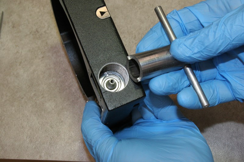
Checking Worm End-Play or “Float”
While everything was clean and still disassembled I thought it would be a good time to take a close look at the worm bearings. One of the things I had been curious about was the quality of the bearings and whether they were sufficiently pre-loaded to prevent end play, or “float” as it is commonly called. End play in the worm can make it look like your drive has excessive backlash between the worm and the worm wheel, even when you have none.
If you find yourself carefully adjusting the worm clearance to the point of approaching a zero-clearance binding situation, but you are still getting a slight movement in the spindle, it pays to look to see if the worm shaft itself is free to slide between its bearings. While the ball bearings used at the ends of the worm shaft are designed for radial loads, they can certainly take some axial (thrust) load and this is used to take up any slop between the worm shaft and the bearing ID as well as play between the inner and outer races of the bearing. The adjustment for end play is found under the domed caps in each of the worm housings.
Setting the amount of preload on these bearings is a matter of feel, and the best time to adjust it is when the worm is disengaged from the worm wheel and the belt is off. The preload drag can be felt by rotating the sprocket with the tip of a finger. Some drag should be felt, but not to the point of any roughness or where it is difficult to spin with a finger tip. If you are feeling roughness or detents from brinelling, this would be where you would start considering replacing these bearings. Although my bearings were smooth, the preloads on my DEC and RA worms were significantly different on my factory-new mount, which implies that the factory probably doesn’t have a terribly sophisticated process for setting preload either. I ended up setting the preload drag of both to a level somewhere between that of the loose one and the tight one. I made a wrench from a piece of pipe to make this adjustment, but others have used pointed nose pliers effectively.
Threaded Ring With Spanner Slots Allows Adjustment of Worm Preload, or “Float”
Tighten or Loosen to Remove End Play in Worm Shaft & Give a Slight Rotational Drag
Reassembly
This is a reverse of the disassembly process but with a few noted precautions.
Prepare each of the thrust bearing sandwiches in a clean area. The grease will help hold them together.
RA Axis Assembly
Begin by brushing a little grease around the aluminum shoulder (the portion concentric to the spindle) where the RA spindle enters the cast housing. Avoid getting grease on the adjacent face of the casting upon which the thrust bearing seats. A thrust bearing cage can contact this shoulder, so it needs to have at least some grease. Slide on one of the larger thrust bearing assemblies. Then apply a little grease to the shoulder of the steel RA spindle as shown and also apply a thin film to the inside mating surface of the brass worm wheel. This grease contributes directly to the drag on the spindles when unclutched, so keep it thin if you want easy-turning axes. Slide the worm on while rotating it to distribute and extrude excess grease. Everything should turn smoothly at this point.
Thin Grease Layer on Shoulder Reduces Drag When Declutched
After the Thrust Bearing is Installed, Slightly Grease the Shoulder of the Steel Spindle
Side of worm with recess faces thrust bearing
Carefully clean up any grease that has oozed out from between the brass wheel and the spindle. Wipe the face of the worm wheel multiple times with solvent and fresh paper towels. This is your clutch face. NO GREASE ALLOWED.
Reinstall the worm housing for the RA axis (with the extra index board) by plugging in the index wire, feeding the encoder wire back through its little hole, and then easing the meshes of the worm and wheel together. Make sure that excess wires are pushed back into the housing body and that they don’t get pinched. Make sure that the worm housing seats properly in place and finger tighten the four socket head screws.
Reattach Encoder and Worm Index Wires
At this point I thought I would begin to set the worm mesh. I put a screw into one of the holes of the worm sprocket to use a crank handle. This is actually a very effective way to feel for binding as you try to minimize the mesh clearance, but in hindsight I don’t recommend doing it at this time as I did. Unless the worm wheel is held tightly against the thrust bearing, the mesh won’t come out right, and you’ll end up trying to optimize something that is going to change later anyway. For now set the mesh on the loose side, and continue with this later.
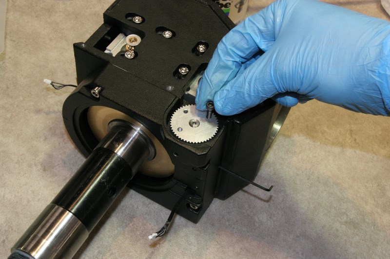
Using a Screw as a Crank Handle to Spin the Worm Gears
Prepare to install the RA spindle into the base casting. It is safest to perform the following steps with the spindle pointing up and the with the body held in your foam vise.
Make sure that there is a thin film of grease on the spindle journals – not slathered on but just enough to prevent rust. Solvent wipe the surface of the brass gear for one last time, and carefully place the clean and dry clutch disk on the spindle journal shoulder that protrudes from the brass worm wheel.
Placing Cleaned RA Clutch Disk
Reinstall the encoder board and plug the cable in. Give the little pink sensor on the encoder board a wipe with a microfiber cloth (in case any grease got on it) and then re-install the cover. Before tightening the encoder cover screws pull the cover as far back in the direction away from the spindle as the holes will allow. This will help prevent the inside edge of the encoder cover from scraping on the base casting near the setting circle.
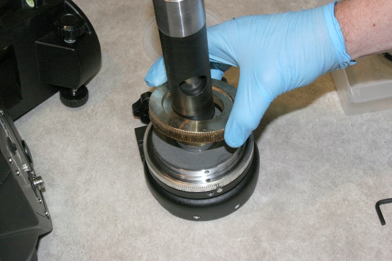
I found that both encoder rings on my new mount had spots of excess grease on them that had apparently been the cause of some repeatable position glitches. Check and if necessary clean the encoder ring on the base casting. I used a bunch of cue-tips for this. Excess grease can be picked up with a dry cue-tip by rolling it as you wipe (always presenting a clean cotton surface instead of pushing the grease along). Repeat this as necessary until any blobs are gone, then if necessary use a few alcohol-dampened (very slightly) tips to pick up the residual film.
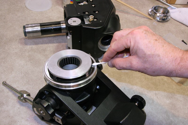
Clean Both DEC and RA (shown) Encoder Rings Before Assembly. Do Not Use Strong Solvents.
Give the flat aluminum surface of the base casting that will contact the clutch disk one last solvent wipe and let it dry. Then slide the inverted base casting down onto the RA spindle being careful to watch alignment as the journals go through the roller bearings. If you try to do this sideways instead of vertically you will have to fight the clutch disk falling out of place off the narrow spindle shoulder.
Cleaning RA Clutch Face on Base With Lacquer Thinner (I’m NOT Greasing It As Picture Might Imply)
It is important now to lubricate the fine threads between the two chrome parts (the 12-hole faceted ring and the mating flat plate) of the clutch lock. What you do here will have a direct effect on how smoothly the RA clutch lever locks. My stock mount came with some lubrication on these threads, but the clutch lever movement was choppy and it just felt dry. Coupled with the grease-contaminated RA clutch disk, this made for a very ineffective RA lock. The chrome-on-chrome threads with the factory grease was not a great combination. I tried a very heavy molybdenum grease and this helped, but it still was not terribly smooth.
What I ended up using was Nye damping grease. Damping grease is commonly used in everything from binocular hinges to potentiometers to give them that silky smooth feel. This material takes some effort to find in small quantities and is relatively expensive. A while back I had ordered a sample evaluation kit of five different grades of damping grease made by Nye Synthetic Lubricants. This was for a different project, but I find myself using this material for many different applications. The kit is very handy to have around if you work with optical accessories such as focusers. For the threads of the chrome clutch I used Nye’s 868 fluorocarbon gel, and the clutch lever is now perfectly smooth with absolutely no stiction.
I bought the damping grease kit shown below from TAI Lubricants (www.lubekits.com) for about $100.
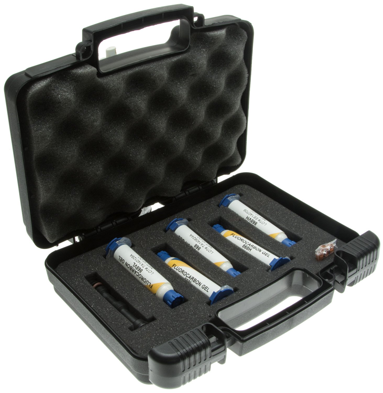
Nye Damping Grease Kit
Once the clutch lock threads are lubricated, thread the faceted lever wheel into place. Just thread it on until it stops, but don’t tighten it.
If everything feels right and the base rotates freely on the spindle, you can proceed. Reinstall the flanged chrome RA clutch lock plate using the four flat head screws.
Reinstalling the Clutch Lock
Inserting Lower RA Thrust Bearings
Next, insert a pre-lubed thrust bearing stack over the end of the spindle. Screw the black threaded collar onto the end of the RA spindle. It will come to a hard stop, and you can either hand tighten it or use the spanner holes to get it a little tighter, but don’t overdo it. The three set screws can then be tightened one at a time through the holes of the chrome clutch ring. The set screws dig into your spindle threads, so don’t go overboard. They only need to stop the collar from unthreading.
You can now turn the chrome ring counterclockwise until you feel some resistance. This resistance is caused by the entire RA spindle being pulled through the roller bearings so that the clutch disk is starting to compress between the brass worm wheel and the body casting. You will choose the correct hole for the clutch handle later.
This completes the RA assembly. The polar scope can be reinstalled now or after everything is finished.
DEC Axis Assembly
This procedure should be routine by now.
Follow the same sequence that was used for the RA axis. Grease the same parts, and keep the same parts free of grease while installing the large thrust bearing and the worm wheel. Hand tighten the socket head screws of the worm housing without worrying about backlash for now. Install and wipe the encoder and plug the wire in. Clean the encoder ring under the DEC setting circle on the spindle assembly.
Degrease DEC Clutch Face
Install Clutch Disk and Worm Wheel
When it comes to inserting the DEC spindle into the roller bearings of the body, you may need another set of hands if you want to lower the heavy base/body assembly onto the vertical inverted spindle. Otherwise you can assemble them sideways with this caution: make sure that the clutch disk has not fallen off the DEC spindle shoulder when you slide the parts together. The disk will probably fall down as you are jiggling angles to get the spindle aligned into the bearings. Just make sure that the disk is tight up against the brass worm wheel as you slide the spindle into the final position. If the disk has fallen off the shoulder as you slide the spindle in, you will deform or cut it.
If everything is rotating freely, you can install the last thrust bearing stack on the lower end of the DEC spindle.
The captain’s wheel clutch lock is another place where the choice of lubricant affects the feel and effectiveness of the clutch. Damping grease is recommended if you have it.
Threads on Captains Wheel Were Coated With Nye Damping Grease, Not Super Lube Shown
Finally the end collar can be threaded over the spindle and the three set screws gently tightened.
This completes the DEC axis assembly.
Adjusting the Worm Gear Clearance
Adjusting the clearance between the worm and the brass worm wheel for each axis requires patience and multiple iterative attempts before you land upon an optimum setting. The mission here is to minimize backlash while avoiding any hint of binding at any position of the worm wheel.
The worm clearance adjustment works by moving the entire worm housing toward or away from the worm wheel. Two recessed set screws in the worm housing on opposite ends of the casting provide a means of pushing the housing in a controlled manner. The four socket head screws that hold the worm housing in place must be sufficiently loose to allow the housing to slide under slight pressure, but you should expect that the backlash may shift a little when those screws are tightened.
There are a few things you can do to make this job easier. If you don’t want to waste dark time you will have to rough this in by feel or you can refine it a bit further by making use of an inexpensive dial indicator. Of course tweaking the backlash while viewing a distant daytime target or a star through your scope will give the greatest sensitivity.
Here are a few tips before starting:
1. Remove the set screws from each end of the worm housings (encoder end and the radiused end) and use a toothpick to put a little grease in the threaded holes, and then reinsert the set screws. The black oxide coating on screws is quite abrasive to aluminum, particularly where they will be worked in and out a lot. A little grease will help.
2. Before putting any loads on either axis make sure that your worm clearances are not too loose where you could possibly skip teeth if loaded or bumped. Also, set the clutches to a light grip for the same reason.
3. For the DEC adjustment, you can feel the backlash movement with greater sensitivity if you clamp something long in the puck rather than just grab the puck alone. I found a metal straightedge that could be clamped in the narrower “V” dovetail, and gently pushing the end of the longer strip gives a better feel for the backlash “click”. A wood strip will work too, but metal transmits the click better.
4. For the RA adjustment, I found that the extended counterweight shaft with the extra extension screwed on serves this function.
5. If you can contrive a support to set up dial indicator so that it contacts your long DEC lever or the extended counterweight shaft, you can visually confirm when backlash is taken up and motion begins. However, neither listening/feeling for a click nor using a dial indicator are as sensitive for detecting backlash as monitoring movement through an attached scope. In any case you want to make sure that you are operating in a balanced state, not east-heavy as you would when imaging. You want to see your backlash, not hide it.
6. I think there is a better method for minimizing backlash in a bench setting and if you aren’t able do actual targeting through a scope. This method doesn’t rely entirely on trying to detect wiggle room in the rotation of the axes, which can be hard to detect with the heavy grease in the worm. Instead you will try to feel for backlash from the worm drive sprocket. It may be tedious, but setting backlash with the belts off by manually spinning the worm sprockets can give you a very good feel for clearances and binding. It gives a very sensitive measure of your backlash, because you can feel the rotation of the sprocket with your finger, and the drag on the sprocket will lighten when you are rotating in the backlash zone where the worm is not actually pushing or pulling the brass worm wheel. With one hand trying to rotate the spindle both ways and the finger on the other had rotating the worm sprocket both ways, you will quickly get a sense of your metal-to metal-clearance. This method is described below, although the mechanics of changing the backlash clearance are the same no matter how you choose to detect it.
Note: At this time we’ll assume that you are satisfied that your worm end play or float is correctly set so that any backlash detected from now on is NOT caused by any linear worm motion. However is important to understand that in this mount design both the RA and DEC spindles will have some slight undesirable radial movement in their respective roller bearings. This, exacerbated by the relatively small diameter of the worm wheels means that you will probably still see some baseline amount of rotation in each axis that may look like worm backlash but will still be present even if you have zero worm end play and zero worm clearance (a binding situation). This cannot be helped and is a consequence of a design that uses straight roller bearings instead of tapered conical bearings that could be preloaded to minimized radial play. Unfortunately, patience and perseverance will only reduce backlash to a point, and then you will run into the fundamental limitations of the design.
Regardless of which axis you choose to work on first, start by using the tip of your finger to rotate the worm sprocket. Rotate in one direction and you will feel when it starts to engage the worm wheel. Now rotate in the opposite direction, and you will probably feel it rotate freely through some angle as it is no longer actually in contact with the worm wheel. As you continue rotating the worm will again engage the worm wheel. If you have a hard time feeling any change, try grabbing the axis to put a little additional load on the worm wheel.
Now assuming the you are feeling some excessive clearance, tighten (CW) the set screw on the rounded end of the worm housing as needed to shift the housing and the worm ever so slightly toward the worm wheel, and recheck the unloaded angle of rotation of the worm sprocket. The angle should be smaller. If there was no movement make sure that the opposite adjusting screw on the encoder end of the worm housing is not too far in and limiting the range of motion. . Repeat until rotating the sprocket in opposite directions shows a small but still barely perceptible “dead band”, where the worm is turning but not moving the worm wheel.
You can now gently tighten the set screw on the opposite end of the worm housing near the encoder. This will probably slightly increase your backlash. From now on turn the two adjustment screws in unison (two allen wrenches helps), tightening one while loosening the other the equal amount. Work these two adjustment screws together as needed to shift the worm clearance to a minimum but perceptible amount.
NOTE: When you are getting down to the optimized backlash settings, don’t think of your screw adjustments in terms of eighths or sixteenths or other fractions of a turn. These adjustments are very small, and near the end both set screws should be applying pressure and fighting each another a bit. Final adjustments are made by increasing or reducing the screw pressure, but never by loosening one screw entirely. Sometimes a minute final adjustment will be made by tightening or loosening one screw only.
When you think you have an optimum backlash setting you will want to check the clearance around the entire circumference of the worm wheel to look for tight or loose spots. This will generally require several hundred turns of the sprocket either with your finger tip or by using a screw in the sprocket hole as a crank. If you find any tight areas due to eccentricity of the worm wheel you will want to readjust the minimum backlash at that spot and accept the looser fit elsewhere.
Finally, the four socket head screws for the worm housing need to be tightened incrementally. You may find that this alters the backlash setting to some degree. You may need to loosen them back up, make a compensating adjustment to the worm clearance, and try again. Or several more times.
When everything is tightened up, do another manual spin of the sprocket for a full turn of the worm wheel to check for clearance and freedom from binding in all positions.
Using a distant target or star to monitor your axis motion will give the ultimate visual feedback on your worm backlash, as long as you can reach the worm sprockets while looking through your scope or you are using some sort of live imaging. You can also do this with the belts in place by slewing with your hand control and observing your motion dead band. But you will have to quantify your backlash in terms of time for a given slew rate, and any binding situation will only be detectable by carefully listening to motor sounds.
Again you will want to have the scope in a balanced state in all axes so that you see your backlash delay whenever you change directions.
Results and Final Thoughts
- The truly periodic portion of PEC (not some average, but the peak to peak deviation) did not perceptibly change after going through this process, nor was there any expectation that it would. That is more of a function of the worm gear quality than a lubrication issue.
- The number of random (non-periodic) angular position glitches did noticeably decrease, presumably due to reduction of grease inclusions on the worm and possibly the thrust bearings.
- The drag on both axes was considerably reduced due to grease removal, and balancing could be accomplished with greater sensitivity.
- The clutches lock and release much more effectively.
- There was a big reduction in backlash, although some eccentricity in the worm is unavoidable and near-binding of the worm in one position results in a peak backlash 180 degrees away.
- Encoder glitches in certain positions went away.
It was a great learning experience to go through this mount and to be able to spend the time tuning and tweaking to a degree that the factory never could or would. If you are reasonably careful and can pay attention to your steps as you disassemble (and perhaps with the help of this walkthrough) there is no reason why you can’t do your own tune-up.
I hope this helps, and have fun!
![]()