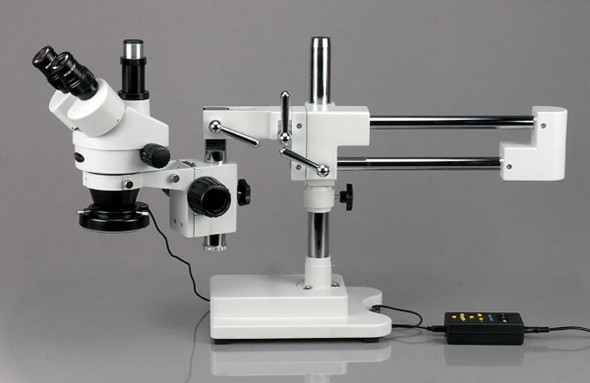
Review: AmScope 3.5x-45x Boom Stereo Microscope
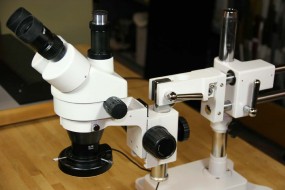
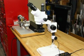
Circuit Board Model with Trinocular Camera Port and 144 LED Ring Light
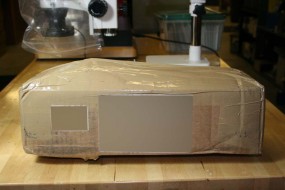
One of the perks that you lose when abandoning the corporate engineering environment is the access to high-end test equipment to use or borrow for your own projects, and one of the things that I missed the most was having a good quality stereo microscope within reach. Working with microwave ICs and picosecond-range pulse circuits required spending a good portion of the work day staring through microscopes while assembling die-level circuitry and performing wirebonding. Microscopes were so common in the workplace that I never really understood how pricey they were until I had to purchase a Leica scope & wirebonder and the ocular-less Mantis for general assembly work in my development lab.
I have always had some of my own basic gear at home – oscilloscopes, a logic analyzer, and other basic equipment – but no network or spectrum analyzers, and no microscope. Surplus name-brand scopes in decent condition can still command high prices, and I was recently looking for a nice used Nikon or Leica when this AmScope stereo boom microscope happened to arrive courtesy of Santa Claus. A few years earlier I had come very close to purchasing a different AmScope model based on a high percentage of favorable reviews. It was a happy accident that the unit received was very close to the one I had considered buying years earlier, and even happier that it was a more elaborate model than I would have purchased for myself.
This microscope with the LED light source was $500 with free shipping, and for that price it represents a very good value. The cosmetic appearance and optical performance are surprisingly good, and the versatility of the boom stand has become more apparent as I use it. There were a couple of issues (tweaks actually) that were easily resolved on my own, but there was one mechanical issue that I consider to be a fairly major design or manufacturing blunder. I will discuss this problem and resolution later.
Mechanical
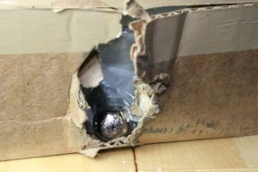
The first impression that I got when unpacking the scope was that appearance of the plated and painted components was better than I expected. Most of the castings were aluminum, although the heavy base and the counterweight on the dual-boom are made of cast iron and the two boxes together weighed in the neighborhood of 70lbs. The castings and the scope body are nicely finished with a textured off-white coating. The exposed metal parts of the boom stand are finished with what appears to be a chrome flash over a copper/nickel base.
Assembly took only a few minutes and typically involved sliding part A on part B and tightening the handles or set screws.
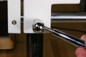
A nice but necessary touch that I noticed right away was that any sliding or rotating component that has a locking handle uses an internal brass sleeve to prevent damage to the shaft or column upon which it is locked. This provides a more secure means of locking the microscope position than would be provided by a soft-tipped locking stud, and you can safely lock the handles firmly knowing that the shafts or columns are protected.
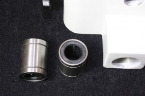
I was also pleasantly surprised to see that the horizontal boom assembly used linear ball bearings for the upper load bearing shaft. Quality boom microscopes use ball bearing slides for their low friction and precision. The lower shaft is used for alignment and locking and does not need ball bearings.
As received my boom had some binding and did not slide freely, but at first I assumed it was a minor assembly misalignment that could be tweaked out. Unfortunately as I looked into this further it turned out that the shaft material used for the upper of the dual booms was undersized and too soft to be compatible with ball bearings. It turned out to be a bigger problem that would require many contacts with the company and a fair amount of work to resolve, and I am pretty sure that this is not an isolated problem. More on this later.
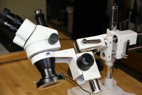
The entire boom mount is very versatile. The short column on the front end of the boom assembly can rotate and lock the microscope body to any angle, and with the dual-boom system the microscope body will be held at this angle for any fore-aft sliding movement or rotation of the boom about the main support column. This is in contrast to the single-boom version that AmScope also sells; that model would also allow angled setting of the microscope body but the angle may not be maintained as the boom is moved fore and aft.
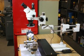
The front column also gives some added coarse adjustment range (in addition to the height adjustment of the main support column) to allow the microscope to adapt to a wide range of inspection heights both above or below the table height. The front column can also be rotated upward to allow the microscope to clear tall objects (such as my micro lathe) although it starts getting a bit high to view through without standing on a pedestal.
Another option was of benefit to me when I was trying to photograph part of the microscope boom itself through the microscope. The whole sliding boom can be removed entirely and the microscope and focuser assembly mounted directly on the base column, making it look more like a conventional microscope. This might be of use temporarily for portability, but otherwise there is nothing that can be reached in this configuration that you can’t view with the full boom in place (unless, as I said, you need to inspect parts of the boom).
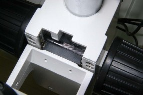
The large-diameter focus knobs turn a helical rack and pinion gear mechanism that moves the microscope mount vertically. Either knob can be used for focusing and as such they work together, however the right knob can be turned independently from the left knob to set the focusing tension (drag). The right knob is tightened against two steel Belleville washers – holding the left knob while turning the right knob clockwise will increase the focuser tension. The tension should be set at the minimum that will keep the microscope body from creeping significantly under its own weight. The focuser is loaded with a viscous damping grease, so this drift may occur very slowly. The knobs are large because the focuser movement is out of necessity quite stiff.
There were a couple of items in the focuser area that were tweaked and these will be discussed later.
Lighting
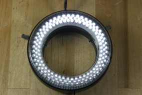
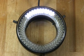
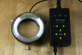
The 144 LED Ring Light (LED-144A) and power source came with my microscope and is highly recommended. Even at a standalone price of about $109 (much less in a package) it is considerably less expensive than the alternative fan-cooled halogen light source and fiber-optic ring illuminator, and it offers a few other advantages. There are ten discrete intensity steps, but the ring light can also be fully or partially illuminated in four quadrants or zones. In normal operation I just keep all of the zones turned on, but in some cases it has been useful to light only one or two to avoid washing out highly reflective parts of the image, such as when inspecting solder fillets. Ultimately you have many lighting options with four independently selectable zones and ten brightness levels.
Subjectively I would say that the color rendition of the LEDs is good, better in fact than the CFL floods that I usually use for photography. A quick comparison of a color chart under the LEDs showed truer reds than the CFL and good color rendition when compared with a daylight source.
Optics
Buying new products that come with defects right out of the box has become so commonplace that I practically dreaded looking through the scope for the first time. Fortunately what I saw was surprisingly good, and with a few adjustments it got even better.
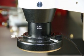
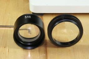
My unit came with the 0.5x Barlow lens, and I’m happy that it did. It is a coated negative focal length lens assembly (it looks like perhaps two elements) that screws into the mount at the objective end of the microscope body. The stereo microscope body itself has dual objective lenses, but the single Barlow lens is large enough that it influences the field of view of both objectives. It reduces the power by one-half, but at the same time increases the field of view, the focal plane distance, and the depth of field. I had low expectations for the simple-looking lens, but once installed it has never been removed. I may need more power at some point, but for now the zoom range is perfect with the Barlow in place.
It should be noted that this microscope requires refocusing when zoomed to a different power. I don’t know much about optics, but I have been inside a higher-end microscope and I seem to recall that it had additional optics and a more complex mechanism to maintain the focus at any zoom level. If you need to change zoom level very frequently on stationary objects this may be an inconvenience. However, if you hand-hold items for inspection this is a total non-issue – the total movement of the focal plane over the zoom range is only about 1/2″ with the 0.5x auxiliary reducer (Barlow) lens in place and less than that without it. Simply hold your object at the focal plane. I tend to use one level of magnification and zoom in only when something requires it. Not having a microscope is a much larger inconvenience that having an affordable one that requires that I refocus under different magnifications.
A closer inspection of high contrast printed material at the highest power (with no Barlow) shows very little chromatic aberration (CA) in the lateral directions. If there is any color fringing at the edges of the field that is not due to my eyeglasses, I can’t see it. The axial CA is a different matter, and it is more visible on certain types of surfaces. Curved or sloping objects show it best: features nearer than the focal plane begin to show blue fringes and those beyond the focal plane have yellow edges. Without a high-end scope to compare it to it is difficult to quantify, but it is not objectionable to me at all. This is caused by lens dispersion and is economically corrected reasonably well with achromatic stacks of lenses, which are probably used in this microscope. This CA effect is also reduced with the use of the Barlow lens on the objective.
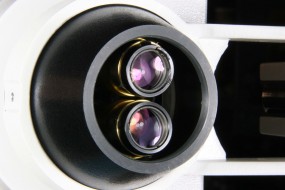
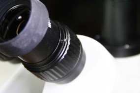
I have read of someone who had a collimation issue with their microscope where the two images presented to the eyes are misaligned, but thankfully I have not noticed anything like that. If any eyestrain is noticed I may have to look more closely at this, but for now it is fine. The interpupillary distance is smoothly adjustable and the eyepieces are linked together to self-center as they should. The rubber eyecups can be left extended or folded back on the eyepieces to allow eyeglass wearers to get closer.
Sample Images
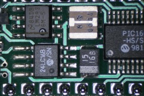
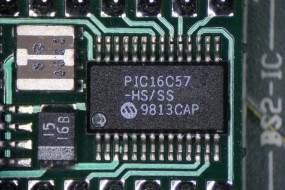
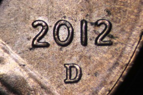
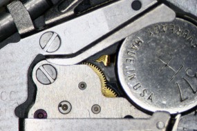
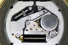
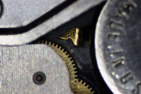
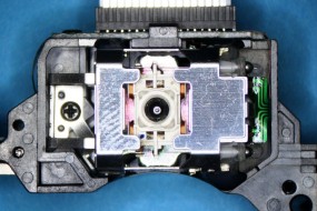
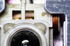
All of these images were taken through the right eyepiece with a Canon DSLR with the kit 18-55mm lens on a tripod. I had intended to make a camera adapter for the trinocular port but a negative lens would be required to fill the camera sensor and avoid vignetting. The AmScope adapter for $89 has a built-in lens but it has received mixed reviews for chromatic aberration.
Tweaks, Problems, and Remedies
Tweaks
-
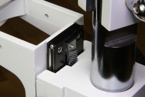
The focuser rack and pinion had a little more backlash that necessary, causing the focuser knob to have a dead band where it would rotate a little before the rack would begin to move. Although I don’t like to see thick, shiny plating on precision components like these (it adds thickness), the rack and pinion engagement seemed smooth enough, so I simply shimmed the rack a very small additional amount toward the helical pinion gear. I did this at both ends of the rack, and the required washers were so thin that I had to work down standard washers on a file. A small strip of metal or card stock could have been slipped under the rack just as well. The focuser now has no backlash and no binding.
-
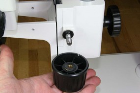
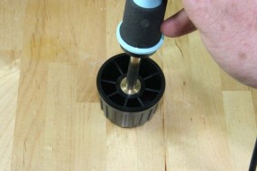
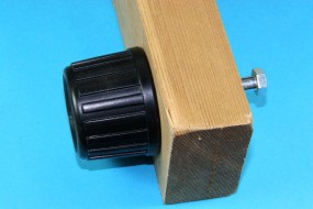
The right focuser knob had quite a wobble in it when I first assembled the microscope. This was caused by misalignment of the brass bushing that is pressed into the plastic knob – this sometimes happens if the bushings are not jigged and are allowed to self-align when being pressed into a plastic part. This was more of a cosmetic problem than anything, but it was easily fixable. A long bolt with the correct thread for the knob was located and a hole was drilled squarely in a thick block of wood. The bolt needed to be snug but free to rotate in the hole. A soldering iron was then used to heat the brass insert just to the weakening point of the plastic, and when that point was reached the knob was threaded onto the bolt and pushed tightly up against the wood block. This squared the knob to the shaft as it cooled, and progress was checked by spinning the bolt to check for wobble and make corrections if needed. Voila – no more wobble…
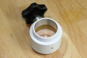
- A plastic threaded adapter supports the LED ring light and threads onto the microscope objective or the Barlow (if used). The diameter of the thread on this piece was undersized and the adapter would slip on and fall off without even having to thread it on or off. I should have mentioned this when talking with AmScope, but I simply added a strip of black vinyl tape to one side of the threads to take up the slop. Somebody didn’t make enough allowance for plastic shrinkage…
-
The eyepiece holders come with a small threaded hole to allow the use of a set screw to lock each eyepiece in place, but no screws were supplied. The hole’s thread diameter and pitch are not specified, (I would think that they are metric), but I found some 0-80 screws that seem to work without any binding whatsoever. With the rotating mount design, I didn’t want to run the risk of tipping the microscope body too far and having eyepieces drop on my concrete floor.
And a Design/Manufacturing Flaw
The issue that I will get into in a moment is not something I would consider an acceptable cost reduction point in the effort to make an economical product; this is a mismatch of materials that causes deterioration of this particular product from the moment you start using it. There is a cheap way to fix it that would reduce costs, and a better way that would cost a little more, but either way it really does need to be fixed. I do not know whether other products are affected.
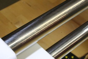
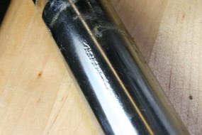
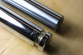
Earlier I mentioned that the steel boom shaft that slides in the linear ball bearings was made of improper material. I first noticed that the shaft was somewhat grooved as I received it and that the sliding movement was rough. Over the next few days I noticed that the grooving was getting worse, so I loosened the screws in the counterweight and front end block and rotated the shaft to a new position, one that presented a fresh, smooth surface to the ball bearing.
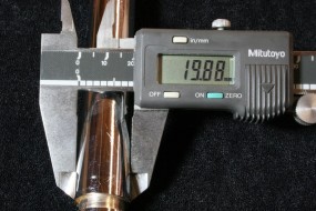
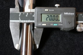
Upon reassembly I noticed that on the first full extension of the boom new grooves formed in the shaft. This is caused when the high pressure of the steel balls in the linear bearings actually deform the metal in the shaft, an effect known as Brinelling. The steel for the shaft was too soft, and it was undersized from the 20mm diameter that the bearings required. The amount of vertical slop at the microscope end of the boom was excessive as well.
I have used quality boom scopes in the past and they have always been built such that they can be moved around smoothly to scan large surfaces without the need to be locked down at the new position. The AmScope boom as received was sloppy enough to require a lockdown once set to the new position, and as movement got progressively rougher with use the action of sliding the boom became a two-handed operation – one to lift the weight of the microscope while sliding and the other to lock the handle.
Steel shafting suitable for use with linear ball bearings must be case hardened and preferably have a ground finish that is accurately sized. A few calls to AmScope resulted in a conversation where I was told that the microscope should have come with plastic sleeve bearings, not ball bearings. This would be less smooth and have more friction than a proper linear bearing and shaft, but at least it would not deform the soft steel with every movement. They offered to send me a replacement boom assembly that they claimed would have the correct plastic sleeve bearings.
What arrived was a new replacement of exactly the same boom with ball bearings and a soft steel shaft – already dimpled and grooved just from the assembly process. After another couple of calls it became apparent that when they thought they were looking at plastic bearings they were actually seeing the black seals on the ends of the linear ball bearings. At this point I was dealing directly with a VP of UnitedScope and discussing options for what I thought needed to be done. He indicated that any changes from the supplier in China would be very slow, and that was assuming they could be convinced that a problem even existed. I made a proposal to make a prototype modification on my own time, and the VP and I agreed on terms.
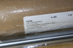
I purchased a 32″ length of the proper 20mm hardened linear bearing shaft from eBay. After a double delay (the first shaft that the bearing manufacturer sent was defective, of course), I proceeded to make a replacement upper shaft. I had expected the prehardened material to be miserably difficult to machine, and I had to use a tool post grinder on my lathe to cut and groove it. I grooved one end before deciding that the remaining set-screw grooves were really not at all necessary.
The leftover piece of hardened shaft was just long enough to allow me to remake the shorter lower shaft as well, so I did. This was not necessary, but it does provide a better fit the hole in the stationary casting with the locking handle. In fact, curiously enough all of the holes bored in the castings were large enough to accommodate the correct 20mm shaft, almost as if the boom had been designed around the correct size shaft but there had been a later substitution of an inferior material. It was quite telling when I disassembled the counterweight casting on the new replacement boom that I would be modifying. The 20mm bored hole was shimmed on one side with a strip of card stock to take up the slop of the undersized, soft steel shaft.
After all of the conversations with AmScope and the task of making the new shafts (which was not very difficult, actually), the microscope boom now slides perfectly as it should. A video comparison of the factory boom compared with my modification can be seen here:
I did all of this in an effort to fix my own microscope but also in the hope that they would use the information to fix the problem with their supplier. I get the impression that AmScope is an importer/distributor without any real engineering group that can address problems like this. I was also left with the feeling that they were more at the mercy of what they were sent by suppliers and that they didn’t exactly have a hotline to deal with newly discovered problems before more units get built and shipped.
Even though AmScope was cooperative and actually generous at times, I did get the sense that there was some disbelief that wider problem could exist when so many units have been sold without complaints. Substitution of an inferior material may have happened recently, but it is not impossible that I may simply have been the first person to notice. I have run into the “nobody else has reported a problem…” scenario a few times before, and there are some pretty interesting stories of engineering blunders to be told (and that’s not even counting my own engineering blunders).
From a customer perspective, AmScope was cooperative and did more than I would have expected. Unfortunately, from an engineering perspective, and despite assurances that they would look at the larger problem, I get the sense that this may get treated as an isolated incident, even though it is clear that the replacement part and probably others in inventory are built exactly the same way. My problem is solved, and I am out a few hours of time but no costs. At this point I believe that changes will only occur if other customers affected by this, if any, take the time to report it.
Summary
As I said in the beginning, I feel that this package including the LED illuminator and the 0.5x Barlow lens is a very good value for the price, even with the flawed boom design. In numerous dealings with support I found them to be willing to talk, generous with replacements, but limited in technical expertise to deal with something out of the ordinary.
The complete specifications for this model taken from the AmScope site are shown below:
Features:
- A 3.5x-45x Zoom Power Microscopy System on Boom with Lighting Intensity and Direction Changeable LED Ring Light!
- Cool, Even, Bright and Flexible 144-LED Illumination
- Allowing You to Change Lighting Intensity and Direction for Best Stereo Images
- Trinocular Design for High Quality Photo, Video or PC Attachment
- Versatile Boom Stand Allowing You to Point Microscope Head in Any Direction You Wish!
- Upright Tube for Camera or Video Attachment
- High Resolution with Great Flatness and Contrast
- Erect Stereo Sharp Images over a SUPER Widefield of View
- Accurate Alignment Ensuring Fatigue-Free Long Time Viewing
- Crystal Clear Original True Color Images
- 45 Degree Inclined Trinocular Head with SUPER Widefield
High-Eyepoint Eyepieces - 30mm WF10X/20 SUPER Widefield Eyepieces (see the difference in the above picture)
- Both Ocular-Tubes with Adjustable Diopter
- Adjustable Interpupillary Distance
- Full Optical Glass Elements
- Precise Ground Glass Lenses
- Heavy-Duty Cast Steel Stand Finished with Stain Resistant Enamel
- Rugged Solid Cast Steel Base
- All Metal Mechanical Components
- Rubber Eye-guards Included
- Manufactured under ISO 9001 Quality Control Standard
- Excellent Five (5) Year Manufacturer Warranty
- Unbeatable Low Price Guaranteed or the Difference Back!
- Satisfaction Guaranteed or Your Money Back!
Specifications:
- Head: 45 degree inclined 360 degree swiveling trinocular
- Eyepieces: 30mm super widefield high-eyepoint WF10X/20
- Objective: 0.7-4.5X
- Zoom Range: 13:1
- Diopter Adjustment: +/-5dp
- Interpupillary Distance: 2-3/16″ – 2-15/16″(55-75mm)
- Working Distance: 4″ (100mm)
- Illumination: 144 White LEDs
- Power input: 110-240V, 50-60HZ, Automatic Switching
- Boom Stand: 20″ double-arm (overall length: 30″), 17″ high pillar, 10-1/4″x8-1/4″x2-0″ solid cast steel base
- Accessories: eye-guards
- Shipping Weight: 75 lbs (Packed in 2 boxes)
Packing List:
- One Trinocular Stereo Zoom Head
- One Pair of Super Widefield High-Eyepoint Eyepieces: WF10X/20
- One 0.5X Super Widefield Barlow Lens
- One Double-Arm Boom Stand with Focus Rack
- One Variable 144-LED Ring Light with Ring Mounting Adapter
- One Pair of Eye-Guards
- User’s Manual
![]()

