DIY Resistance Soldering Outfit
Put Soldering Heat Where You Need it – Now!
Resistance Soldering
Resistance soldering is a process by which objects to be soldered together are heated by passing a current through them rather than by applying heat from an external source. Localized heating is caused by relatively high current passing through the resistance of the junction. As long as the heating rate of the junction exceeds the thermal dissipation rate, the temperature will rise high enough for solder to melt and flow.
There can be several advantages to using resistance soldering for certain applications, but two big ones stand out:
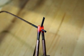
- Speed – a resistance soldering unit can generate heat in a localized spot much more quickly than application of a 700 to 800 degree soldering iron which relies on conduction for heat transfer. A resistance soldering unit can also exceed soldering temperatures, heating a junction to bright orange, actually welding small parts together.
- Steep temperature gradient – because of the rapid heating of the joint being soldered, it is possible to obtain a very high temperature gradient over a short physical distance, making it easier to prevent nearby solder joints from melting and falling apart. This makes it attractive for sequentially soldering intricate pieces together.
The equipment used for resistance soldering is similar to that used for spot welding except that the required currents are much lower. Resistance soldering of electrical devices is generally not recommended due to the risk of damage to the part from the applied current.
Commercial resistance soldering equipment can be purchased á la carte or as systems that consist of a power sources and probes or tweezers designed to apply current through a joint. American Beauty is one manufacturer that offers everything from micro-capacity up through heavy-duty plumbing systems, and their site is a good source of information for choosing a system to fit your needs.
Power sources generally come with infinitely variable adjustments now, although older or inexpensive units may be found that have fixed settings or sometimes with taps to allow multiple heats settings (current settings). The wattage of the power unit (and the probe selection as well) will dictate how large or how thermally conductive the objects to be soldered can be. 250 watts is a common hobby size. 100 watts would probably handle light work (like wire art), and the heavy-duty units in the 1800 watt range could handle much more.
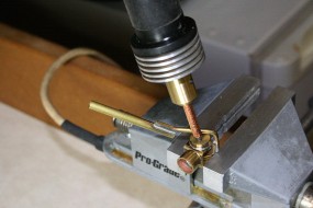
Probes and tweezers come in a variety of sizes. A single tip probe looks like a soldering pencil but has a tip of stainless steel or copper-clad carbon; it is intended to apply current to a local spot. This type of probe is a single lead device, and the object to be soldered must be connected to the other power source lead through a metal bench top, wired vise, a pan filled with conductive padding, or by clamping a lead to the object itself. This connection to the object must be of low resistance, otherwise it will itself heat up.
Resistance soldering tweezers are two conductor devices and are very handy to use because they can help hold parts together while applying the current right where it is needed. Small tweezers can use stainless steel probes, either flat or pointed. Larger tweezers can use carbon jaws, where the larger size allows the fragile carbon to have sufficient mechanical strength.
It should be noted that heat is not only generated because of the resistance between the parts to be soldered. Compared to copper, stainless steel is a poor electrical and thermal conductor, and carbon is even worse. This makes stainless probes and tips generate their own heat, and carbon will often glow at the contact point. Some heating of the junction to be soldered will be caused by thermal conduction from the hot probe tips, so in effect you have resistance soldering with a little conventional conduction heating thrown in.
Resistance soldering complements conventional soldering – there are applications where one method is clearly preferable over another, and sometimes either process will work equally well.
Building a System Versus Buying
A commercial 250 watt unit with tweezers and a foot pedal runs in the $450 to $600 range. Prices for used systems on eBay can still be remarkably high. If you need a unit to put to work now, or if you would have go out and buy every component that you would need to build one, buying new or used may be the way to go.
However, if you already have a stockpile of electrical parts and materials, you might be able to build your own for next to nothing, as I did. Of course I’m not counting the cost of labor and the cost of stock items that were purchased previously, but that is the joy of DIY – thinking you got away for free.
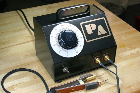
The system that is shown here required an outlay of less than $40, but I’ll admit that I started out with an old variac, a transformer suitable for rewinding, miscellaneous minor components, and metal stock. All I actually had to buy specifically for the project were a few feet of 6 gauge wire for the transformer winding, the carbon rods for the probe tips, and a foot switch. None of the components needed to make a power source and probe tip are terribly critical and can be found in surplus stores or on Craigslist, or maybe even in your own stock.
The Power Source
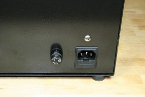
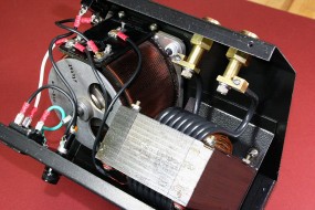
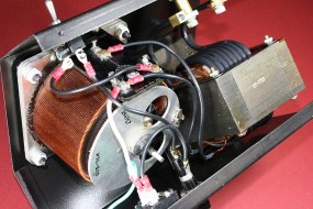
The power source is a very simple design. It consists of a high current, low voltage step-down transformer, some means of controlling it such as a variable autotransformer (variac), a fuse or circuit breaker/switch, and something to house it in.
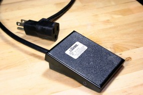
The power unit should plug into a foot switch which is then plugged into the wall. The toggle switch on the power source is used for master power and is left ON during use; the foot switch is used to apply current to the tweezers or carbon-tipped probe.
Transformer Selection
WARNING: to provide proper line isolation, a transformer must be selected that has separate primary and secondary windings without any interconnections between them. Do not use an autotransformer.
Resistance soldering power units seem to run lower voltages than can be easily found in surplus store transformers – I was looking for a transformer with a 3 to 4 volt output. I would have settled for a 120 volt to 6 volt step-down transformer in the 250VA range, but none were available at the time. I think I ran across a web article where someone used a modified microwave oven transformer, but the only dead microwave I had at the time was of the inverter variety, which doesn’t have the big transformer core that was needed.
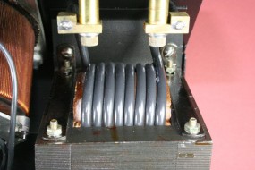
Digging through my transformer tub I did find an almost new 120V to 60VCT @ 6 amp transformer purchased for an old college amplifier project, probably paid for with earnings from visits to the campus blood plasma center. The 60 volt secondary winding was nearly useless for anything I could imagine these days, but the primary and the core would satisfy my 250 watt goal and then some. It also looked like it would have enough space after the secondary was removed to wind the number of turns of heavy wire that I thought I would need to obtain a 4 volt output.
The paper winding cover was peeled off and the secondary coil removed completely. Since I had no way of knowing how many turns of wire were used on the primary winding, and therefore how many I would need to wind for the heavy gauge secondary, I determined it experimentally. To speed things up I wound 10 turns of a lighter wire (# 14 from a length of Romex) around the core and measured the voltage with the primary connected to line voltage. Ten turns gave an output voltage of just under 5VAC, which calculates out to 0.5 volts/turn. Since in ideal-transformer world this parameter is the same for the primary, the measured line voltage of 120VAC told me that the number of turns on the primary was approximately 240, which is irrelevant at this point because volts-per-turn is all that was needed.
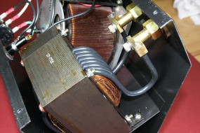
Since I was aiming for 4 volts output, I planned to use a secondary of 8 full turns. I picked the largest stranded wire gauge that could fit 8 turns in the core opening, which turned out to be #6 single conductor THHN rated for 90C and 75 amps in air. There was no worry about temperature rating using this wire even in a close wound application given the low duty cycle usage.
Wrestling the wire through the core holes to make a neatly wound secondary took a little bit of effort, some wood blocks, and a rubber mallet. The wire was stiff, and a little pre-bending helped it conform to the primary winding. Wood blocks and wedges helped keep the wire in place if the core had to be put down from time to time.
When the 8-turn winding was in place four wood wedges were cut to fit and hammered into the spaces between the windings and the core, securing the springy coil. A couple drops of cyanoacrylate bonded the lead-in and lead-out wires to their neighbors. A quick check showed – no surprise – 3.97 VAC output.
Variable Power Control
The full-range variable power control allows you to set the transformer primary voltage anywhere from zero to full line voltage. This in turn varies the secondary voltage from zero to the full step-down voltage, allowing the soldering current to be adjusted.
I chose to use a variable autotransformer (variac) for the power control, primarily because I had one handy. It was rated at 8 amps (I only needed about 3 amps), so it was larger than necessary but it worked out in the end. An autotransformer actually changes voltage in very small discrete steps, and provides a sinusoidal output with good transformer regulation.
Although I have read of other builders using standard light dimmers successfully for control of power output, I was leery of doing it. These dimmers usually specify resistive loads only, and while the transformer primary does appear largely resistive when the secondary is resistively loaded, the primary looks inductive if the secondary is unconnected, or if your probe or tweezers slip off the parts momentarily. If this is the route you would like to go, it would be worthwhile to do a little research and see what has worked successfully for others.
Electronic controls such as dimmers work differently in that they change average voltage by adjusting the duty-cycle of the 60Hz line voltage waveform. The dial will adjust what percentage of each cycle that the output voltage is turned on, and because of this the output is non-sinusoidal and can be full of harmonics. The sharp rise or fall times of the truncated cycles can result in high voltage spikes with inductive loads. Non-inductive loads (such as the lamps that lamp-dimmers are designed for) don’t care – they only respond to the average voltage.
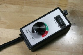
I would still consider it worthwhile to try a lamp dimmer, or go one step further and use one of the electronic router speed controls that are available from time to time for about $15. These are rated for inductive loads, and the 15 amp current rating should represent enough overkill to tolerate almost any abuse. Be aware that the router control pictured (available from Harbor Freight and which I have not tried for resistance soldering) does not go to zero at its lowest setting. There is a tweak posted somewhere on the web that will extend the low range.
WARNING: neither a variac nor an electronic speed control will provide line voltage isolation
Soldering Probe and Tweezers
From the beginning I knew that tweezers and a carbon probe would be essential. Tweezers in particular are very fast for soldering structures together, such as for wire artwork, sculpture armatures, miniature railings and trusses, etc. The carbon probe gets used less but it handles very much like a conventional soldering iron, and it is blazing fast.
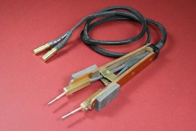
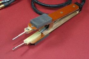
The tweezers shown here were modeled after commercial models that were found on the web. The spring handle/hinge is made from a folded strip of .050 phosphor-bronze with two .125″ thick phenolic strips mounted to it.
The brass blocks that hold the tweezer tips are mounted on the phenolic (insulated from each other and the spring hinge) and the wires are soldered into holes drilled in the ends of the blocks.
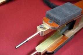
The holes for the needles are drilled at an angle so that the tips of the probes meet, and a set screw holds each tip tightly in place.
The tips themselves are made from 3/32″ stainless steel welding rod cut to length and either flatted or pointed on the ends. Flatted tips are a little easier to use because they are more stable for gripping parts. The stainless rods are slipped into 1/8″ OD copper tubes which are then clamped tightly in the brass blocks by the set screws. The copper sleeves serve a purpose: they improve the electrical conductivity up to the very end of the stainless rod and add a little rigidity to the tips. Copper clad stainless probe tips are available to buy, but these made from welding rod cost virtually nothing and there is no hesitation about customizing them with a file if needed.
The use of stainless-activating fluxes will allow solder to adhere to the tips and generally gunk them up. A thin flat file can be pinched between the tweezer tips and worked back and forth to file new clean and parallel faces.
For the leads I went a little on the light side for flexibility and used 14 gauge super-flexible silicone wire. This wire is available from hobby shops for use on high current electric motors for RC cars, planes, and helicopters. It might have been a better choice to use 12 gauge, but I used what I had.
The tweezer assembly shown with cables, shorted together at the tips, has a total resistance of .05 ohms, which gives a maximum soldering current of 80 amps-plenty for most things, but the transformer could safely supply more current. Actually a better decision might have been to put an extra turn on the transformer winding, giving a little higher voltage to offset the 14 gauge lead losses.
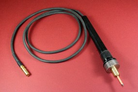
The carbon tipped probe was easier to make. While others have successfully used inexpensive soldering iron handles, the pictured handle was turned from a piece of acetal rod. The diameter was necked down at the grip area and a silicone sleeve forced over it to make a soft grip.
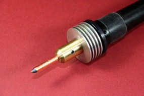
A 1/2″ brass rod was turned to the shape shown and bored at each end. The end of the brass inside the handle was drilled to created a solder cup for the #10 wire attachment, and the tip end was drilled out to a 5/32″ diameter. A solid aluminum heat sink was bored out for an interference fit on the brass sleeve and pressed on with an arbor press. The heat sink helps keep the grip from getting too hot.
The lead wire was soldered into the brass sleeve and fed through the acetal handle. The brass sleeve was then pressed into the handle.
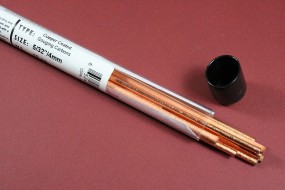
The copper-clad 5/32″ carbon tips are made from gouging rods available at welding supply stores or McMaster-Carr.
About Wires and Connections
The most important thing to remember in building a resistance soldering outfit is to make sure that the highest resistance in the circuit occurs at the solder joint and the probe tips. Careful attention must be paid to minimizing the resistance of every connection and cable in the current path of the secondary circuit.
With a sinusoidal AC waveform, the RMS power dissipation in Watts across any resistance in the secondary circuit is I2R/2, where I is peak current in amps and R is the resistance in ohms. The power dissipated in a resistance will result in a temperature rise based on the specific heat of the material and its thermal mass, the thermal dissipation of the structure being soldered, and a few other factors.
If you are winding your own transformer secondary, consider using the largest copper wire that will fit in the available space with the required number of turns. This will minimize the resistance of the secondary, making it a better voltage source and increasing its short-circuit current. Aluminum wire is not recommended due to its lower conductivity and the difficulty in soldering to connection lugs.
Design the connections for the probes such that they are not the weak link in the current path. Forget about using any type of banana jacks or normal binding posts – think big and massive, and consider of the cross sectional areas of every segment of every conductor that current passes through.
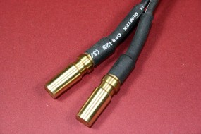
I chose to make solid brass tapered male and female connections to ensure low resistance, based on the commercial designs that were copied. The taper is unique and replicating it would be difficult, so extras were made in case additional probes are needed at some point.
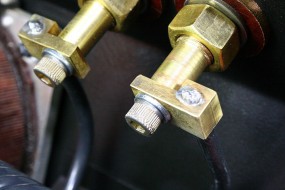
A simpler, though less convenient connection could use hefty brass or copper studs and nuts on the front of the power unit enclosure, with heavy solder lugs on the probe leads. Connections should be soldered, not crimped, and solder joints should be larger than the cable conductor sizes, with generous fillets. The poor conductivity of the solder joint needs to be offset by making sure that the cross-sectional area of the solder is correspondingly larger in area.
Even if copper and brass connections are not available to you, large steel hardware could be used. Stainless steel would be the worst choice, as its thermal and electrical conductivity are worse than plain steel. A good place to look for copper and brass hardware is McMaster-Carr online or around the service entrance panels and hardware in home improvement stores.
The same rules hold for connections at the probes – make sure that there are no crimped connections and no constrictions in the cross-sectional area of any current paths. Choose the largest wire gauge that you feel will offer the flexibility to manipulate the probes effectively. Look for wires with soft insulation (like silicone) and very high strand counts of small gauge individual conductors for maximum flexibility. And keep you cables short. Force the weak point in the conduction path to at the joint to be soldered.
Primary Current Protection
A fuse and a power switch, or a switch/circuit breaker should be added in series with the hot side of the line voltage where it feeds into your power control device (variac or SCR control). A starting point for the fuse or breaker current rating would be the transformer’s volt-ampere rating divided by the line voltage. If you are using a very large transformer (oversize for your typical needs) you may want to fuse it at a level below its capacity.
Case and Cooling
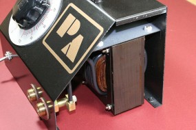
I folded up a custom case from .040″ steel sheet and spot-welded a few brackets in place to mount the transformer and to interlock the case halves. The upper part of the case screws to the lower part with the same four screws that hold the rubber feet in place.
I have no cooling holes because 1) I hate drilling lots of holes, and 2) bench testing of the transformer under load showed very little heat generation even with fairly heavy usage. If you use a smaller transformer and push it hard there will be heat generated in the windings and you will need ventilation. Anticipate the need for a case with perforated or expanded metal covers and bottom to allow convection air flow.
The dial for the Variac knob was drawn using TurboCad, printed on glossy photo paper, and laminated with protective film,. After it was cut out a little oversize it was glued to a disk of aluminum, finish sanded, and screwed to the front of the metal case.
BTW, the PA letters were initials of a domain name that I no longer have. The decal was cut on a vinyl cutter and was put there because the case looked like it needed something to fill that spot.
General Transformer Tips & Trivia – Afterthoughts
Note: some of the concepts below apply to ideal transformers; these are theoretical models that have no losses, perfect coupling, and infinite inductance.
- Assuming your requirements are not excessively light or heavy, ideally a transformer suitable for use without modification in a resistance soldering power unit should have a line voltage (either 110VAC or 220VAC) primary winding, a secondary voltage of around 6 VAC, a secondary current rating of 20 to 50 amps (or more), and a rating of 100VA (volt-ampere) minimum, with 250VA on up preferred. Higher secondary voltages such as the more common 12VAC can also be used as long as the current or VA ratings are still adequate, although low voltages tend to produce less arcing and pitting at the probe points.
- Do not use autotransformers regardless of the VA rating or output current rating; they do not provide isolation from line power and would present a danger of electrocution. The transformer must provide isolation between the line voltage primary and low voltage secondary windings.
- Just so you know what to look for, suitable resistance soldering transformers tend to be at the larger end of transformers that you will usually find in smaller surplus stores. The 350VA transformer that I modified in this project had a laminated core that measured 4.5″ H x 3.75″ W x 2″ T, not counting the size of the coils. High VA ratings mean heavier wire and more iron. There is no harm in using a somewhat larger transformer with higher VA or current rating other than size/portability issues and the need to fuse it properly to avoid overloading whatever you use for probe cables.
- Battery charger transformers are one of the more readily available sources for inexpensive transformers that can be removed and used unmodified (look for a 6V charger, but 12V can be used). Larger filament transformers for powering vacuum tubes are another possibility, but they are obviously getting a bit hard to find.
- The primary of the step-down transformer will consist of many turns (Np) of wire. The secondary will consist of a smaller number of turns (Ns) of wire. The number of turns on the primary divided by the number of secondary turns is the turns ratio (N). Therefore Np / Ns = N . As an example, let’s say that for the primary winding Np is 240 turns and for the secondary winding Ns is 8 turns. The turns ratio N is 240/8 =30.
- Transformers are bidirectional: a step-down transformer can be reversed and used to step-up voltages. A 10:1 ratio, 120V primary to 12V secondary step-down transformer used in reverse will output 120V from the primary if 12V is applied to secondary.
- The turns ratio also represents the input to output voltage ratio in our ideal step-down transformer. If the applied input voltage is 120V, the output voltage will be 1/30 of that, or 4V. Step-up or step-down always refers to the primary-to-secondary voltage conversion.
- While step-up and step-down nomenclature refer to the voltage conversion, current conversion is the opposite. Any current in the secondary winding of the step-down transformer will appear as a smaller current in the primary, equal to the secondary current divided by the turns ratio N. The opposite is true for a step-up transformer.
- An ideal transformer model doesn’t consider things like the effects of winding resistance, but a real transformer has those losses. This is why in a real transformer the higher voltage windings (low current) will use lighter gauge wire than the lower voltage windings, which will have heavier gauge wire to carry more current.
- Transformers also are used for impedance matching and transformation. While voltage and currents between primary and secondary windings are scaled by a factor of the turns-ratio N, impedances are scaled by a factor of N2. Consider a 5 ohm load resistor connected across the secondary (lower-turn winding) of a N=10 step-down transformer. Looking into the transformer’s primary (higher-turn winding), the AC impedance will look like 5 x N2 or 5 x 100 = 500 ohms. An AC voltage applied to the primary winding will result in the same current as would flow through a 500 ohm resistor attached to that voltage.
- As an extension of the previous concept, a real transformer with no load on the secondary will draw very little current on the primary and consume very little power. Applying this to the previous example, an open secondary (no load, infinite impedance) will be seen at the primary of the N=10 step-down transformer as infinity ohms x N2= infinity ohms. This means that the current through the primary winding is zero if the secondary winding is unloaded. In a real transformer there will be some losses and some currents, but they are low. This is why simple transformer based wall-wart power supplies that are common for powering and charging electronic devices will draw little current and run cooler if they are unplugged from the device.
- Transformer regulation is a measure of how stable of a voltage source the transformer output is under load (not to be confused with active voltage regulation used in power supplies). A transformer with a 99% regulation would result in very little voltage drop under load compared to one with 50% regulation. Examples of transformers with good regulation are line (power pole) and power supply transformers. Doorbell and neon sign transformers have poor regulation.
![]()

