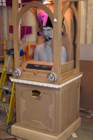
Building a Working “Zoltar Speaks” Fortune Teller
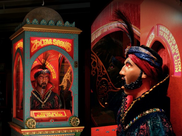
Full-Size Replica of the Fortune Teller in the Film BIG (1988)
Sometime in the late 1970s I became fascinated with researching and collecting antique game machines, candy vending machines, and other amusement devices. My interests were at first focused on those machines that I vaguely remembered from rare visits to a penny arcade as a youth in the ’60s, and even then I was drawn to the artistic design and mechanics of the earlier designs with their art deco lines or ornate castings and wood cabinets. It wasn’t until I started locating information and pictures of these early amusement devices that I became more consciously aware that I had personally encountered many of them at fairs, in drug and dime stores, and in the local movie theater lobby.
Even in the ’60s, the penny arcade that traveled with the amusement show for the annual county fair was loaded with machines that dated back into the early ’30s, and possibly even earlier. By the time I developed the bug to start seeking out and collecting items from this era the market for coin-operated collectibles was hot and getting hotter, due in part to west-coast publications and shows that were fueling speculation and driving prices upward. I began attending the more sensible (and closer) Chicagoland Antique Advertising, Slot-Machine, and Jukebox Show held at the Chicago O’Hare Expo Center and later at a resort in St. Charles, Illinois, and over the years I would usually bring back a few items to add to the collection.
Antique fortune tellers always held an appeal, although it was probably more through association with the other collectibles that I was seeking rather than through any direct experience that I may have had with them in earlier years. A few fortune tellers could generally be found at the Chicago shows in the ’80s and ’90s, but the more elaborate early models were extremely rare and had price tags commensurate with that rarity. And as is the case with many collectibles, you can’t buy just one; the real beauty comes from displaying a collection of several different types. Each has its own features that make it attractive, and there are very few machines that have all the attractions.
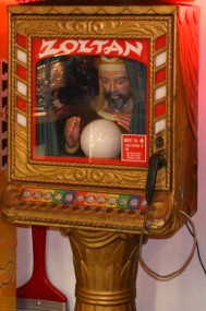
When I first saw the Zoltar Speaks fortune teller in the film BIG (1988) I probably knew that it wasn’t a real antique machine, but it certainly looked authentic. It had almost everything that an antique fortune teller should have – the overall design was fantastic, more unified and more ornate than anything seen before, and it had a serious and slightly ominous presence that made it especially appealing. Even though it is not really a fortune teller – it’s a wish granter – it fits the general category.
I had thought for years that building a full-size fortune teller would be a fun project, and after studying the machine in the film for some time I decided that this would be the one to build. It would be a challenge, and while many of the design and fabrication tasks would be familiar, figure sculpting and fabrication of more complex silicone molds would require learning new processes.
Getting Started
At the time that I began tentatively designing the machine, the only visual information available for guidance came from marginal-quality screen captures made from a VHS tape. Even the DVD was not yet out, and the more useful high definition formats would not be released until after the project was completed.
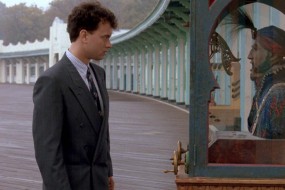
Images were gathered and cross referenced, measured, and scaled in Photoshop against Tom Hanks’ height (published on IMDB), using the one series of images where he appears standing in front of the machine. Shots of the machine’s exteriors included in the film were surprisingly limited in scope – most views were either straight frontal or side shots, and the total amount of screen time was actually quite short. Details of the lowest and uppermost parts of the cabinet were nonexistent.
Fortunately over the duration of the project two other sources of information became available. The first was a commercial showing on the Fox Movie Channel around this time period that filled in at least one missing detail. Tom Rothman, CEO of Fox Filmed Entertainment, was hosting a series of shows called Fox Legacy, and the ads for the program included the original Zoltar movie prop (or one of them) featured on the set. There was just enough of an overhead shot of the dome and cap that I was able to get some idea of how it was constructed.
The second new source of information came from the extras on the two-disc DVD set. Although I had hoped that more information about the prop would be featured, most of the extras consisted of interviews. Nevertheless, there was a short sequence of previously-unseen clips of a machine (curiously it appeared slightly different from the prop in the film) that did help with some details.
Some cabinet features could only be observed in long shots in the film and had to be based on impressions more than anything. It was only a couple of years ago that someone on YouTube pointed out that the original prop is now on display at Garry Marshall’s Falcon Theater in Burbank. If motivated I could probably just go examine it, but that wouldn’t be wise unless I was in the mood to start remaking things.
Before jumping into the (long) description of the design and build process, here are two videos of the replica that were taped when it was first completed in 2008. The first was taped at Kilroys in Minneapolis (with the help of owner and friend Kevin Hammerbeck) and was an amateur attempt to duplicate some of the same shots used in the film:
This second video is a somewhat random compilation of the only video clips of the mechanism that are currently available. These shots were also made shortly after completion of the machine and are in standard definition video and are of marginal quality at times. I would like to take some better HD video the next time I have the machine apart:
Testing the Waters Before Jumping Into the Project
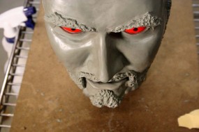
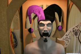
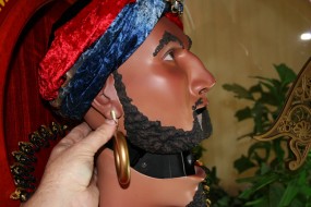
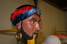
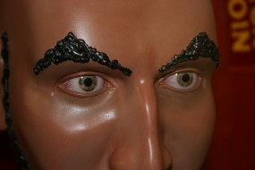
The most logical starting point was on the critical effort that would determine whether the project would go very far – the sculpting of the head. Sculpting was something I had never tried and it was difficult for me, particularly the first time. And it shows. You can look at faces all your life, but until you are forced to try to replicate one out of clay you don’t realize how little you know about the basics.
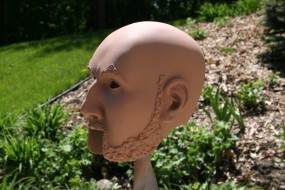
Rather than take the proper steps of learning a little about facial sculpting, I took the engineering approach – using scaled templates, calipers, photo comparison, etc. Even with these tools I made all of the common beginner mistakes, and when I thought I was getting very close to a final sculpture I ended up making some pretty major modifications to everything – eye positions, nose shape, cheek contours, etc. Based on more recent and clearer images of the head, it looks like the original nose was straighter and my first attempt before the changes would have been better. But at the time I was working from a fairly blurry profile image, and I was absolutely convinced that the ridge of the nose had more bumps as you see in the pictures. With only frontal and profile information from the film and absolutely no sculpting experience or anatomical knowledge of any sort, I had to rely on things like lighting shadows to help develop some of the facial contours, and this both helped and hindered progress.
In the end I created a head that is clearly amateurish, although it is not entirely out of place on a machine like this. Original figurative machines were often designed and fabricated by mechanics, not artists, and in that context my sculpted head reasonably blends in with some other rather crude stylized animated figures of this era. I recognize that it is not a good likeness of the original – making a head that looked like the same person was my goal, and in that goal I failed. I have gained a huge respect for anyone with the skill to sculpt a recognizable figure; for some of us just making something that looks like it could have randomly occurred in one of seven billion potential humans is difficult enough. After having had some more practice, I think I could do a better job today, and although the option of remaking the head is always available it probably won’t happen.
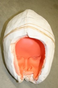
Aside from the artistic shortcomings, there would be other problems due to inexperience. I had created the original sculpt out of Roma Plastilina clay, and with its sulfur content it was incompatible with the platinum-based silicone mold material that I intended to use. The only way I could salvage the clay sculpture was to make an initial mold out of air-cure silicone and make a new molded pattern from that. This actually worked fairly well, and with a resin head casting I was now able to refine the details to a higher degree of finish in preparation for making the real mold.
Some figure sculptors like to rough out a head and face early in the process – it provides a focal point for the rest of the figure. Having a usable, albeit imperfect head within reach performed the same function on this project – it was something to build around and it made the rest of the project look easier, and in fact it motivated and elevated the complexity of the design far above what I had originally envisioned.
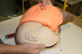
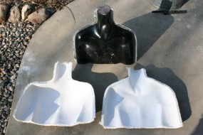
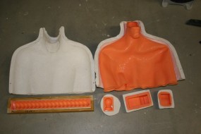
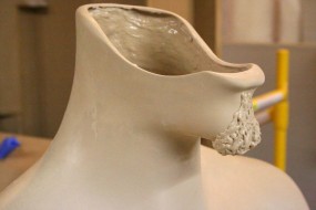
Creating the upper torso was as foreign to me as facial and head sculpting, but at least in this case the shirt would hide any misdeeds. I sculpted the original pattern out of foam and gave it a hard and smooth finish prior to making the intermediate mold. The chin and lower lip piece was sculpted and molded separately and added to the torso pattern prior to making the final silicone mold.
When I look at the nude head and torso now, I see all the proportion errors. but the turban and shirt make them more acceptable. It is what it is, or it was what it was, and with these two potential show-stoppers behind me it was time to get on with the rest of the project.
While contemplating all of the tasks that had to be accomplished to design and build something for both appearance and functionality I had informally established some guidelines, all of which fall under the heading of….
Design it For the Future Collector or Restorer
Barring any catastrophic loss is not really presumptuous to think that any number of individually-made pieces produced today will be in the hands of collectors in a hundred or more years, unless we have split into Morlocks and Eloi by then as we sometimes appear to be headed. Many of today’s collectibles are one-of-a-kind, handmade, of unknown heritage and devoid of any trackable history, and are sometimes classified under the folk art umbrella.
From a longevity standpoint this means that use of limited-life materials or components in the construction should be avoided as much as possible. Key electronic components and even incandescent light bulbs will no longer be available in the future. Even simple things like certain types of machine screws and small hardware items that were available only 40 years ago can no longer be found, and obsolescence must be anticipated going forward.
Having some experience with difficult restorations has helped give an appreciation for what can and can’t be easily repaired or remade. Nearly anything mechanical can be replicated or restored in the future as long as the original part is in a condition to be studied or copied. Any electrical components or electronics which are obsolete and not repairable can be replaced with new and current designs as long as hooks are built into the fortune teller’s design to allow interfacing, and providing that these hooks are documented adequately.
It was with this philosophy that I decided to make the basic operation and gameplay of the machine entirely electromechanical, despite the fact that it would be much more difficult to implement than a design based around a programmable microcontroller. The only concession in using obsolescence–prone electronics would be for some optional higher functions and for the incorporation of music and sound into the machine’s operation. In particular, a separate module was envisioned to contain a microcontroller and sound reproduction electronics. This module could fail or be removed completely without affecting the basic operation of the machine, and ultimately this entire module could be redesigned around future components to perform the same function as the original without any change in appearance.
Lastly, I wanted the machine to look reasonably like a vintage machine of the early twentieth century, particularly in the mechanism. There would be no shiny zinc-plated philips-head screws, wiring would have cloth insulation and be formed into bound harnesses, and any electronics (if used at all) would be hidden behind covers. Metals, wood products, and fabric would be favored. Use of plastics would be limited, but urethanes are considered a superior material to plasters or paper maches and would be used for some of the molded parts.
In any event the materials chosen for use must survive long enough to allow reproduction in the future before turning into powder in someone’s hands. And from the standpoint of appearance, nickel plating, bare brass, hammertone paint finishes, and vintage electrical components were all good; tie wraps, latex rubbers, plastic-insulated wire, circuit boards, and flashing LEDs would be avoided or hidden.
In the end I broke a few of my own rules, but not many.
Gameplay Concept and Functional Design
Since the fortune teller in the film was a prop and not a functional machine, a lot of thought had to be given to how to make it into a plausible game that would be functional enough to actually entice someone to play it. Manually aiming a coin to hit an open mouth target seemed reasonable enough, but in early tests it turned out to be more difficult than expected.
A mockup was assembled using a dummy wood coin ramp and a torso and head with the mouth propped open. The ramp was grooved to guide the coin on its edge as it descended the curve.
At first the coins wouldn’t even reach the short distance to the mouth, and the starting height for the ramp could not be raised for reasons of appearance. I think this was the only time I was ever forced to invoke first-year Calculus on a home project – a curve that would maximize the range of the coin trajectory had to be calculated and cut into the wood ramp. The high-to-low and left-to-right ranges of coin ramp motions that would result in a coin hitting the rather small opening were mapped out, and a considerable extra aiming range was added to this window to make aiming more difficult.
The real problem came with the timing of the coin release if the mouth was allowed to open and close. Due to the inertial delay of the coin accelerating to speed down the ramp and to the launch point, hitting the mouth at its widest opening would require releasing it about a quarter cycle before – when the mouth was approximately half open. This would add another dimension of difficulty to the game, and one that I didn’t think that it would be fair to assume that an average player could anticipate.
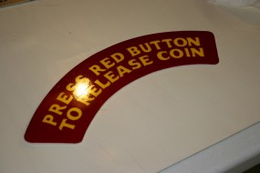
At this point I decided to take the timing away from the player, leaving the ramp aim as the only player variable. The plan was to design the play sequence so that when the rightmost annunciator panel lit up with the message Press Red Button to Release Coin the front button would become active and capable of latching a relay when pressed. Once the button press was detected and latched, the coin release would be delayed until the next available time – approximately one-quarter cycle before the mouth was fully open. If anticipated correctly and the button was pressed at exactly the right time or slightly before, the coin would release almost immediately. If the button was pressed when the mouth was past halfway open, the coin would hold until the next head cycle and then release when the mouth opened half wide.
This was exactly how the machine timing was implemented and it has always worked very well. Since there are no written instructions on the machine other than the directions given on the lighted panels (nor would detailed instructions necessarily be read anyway) this confuses players once in a while, and they will repeatedly peck at the button. This is fine – the button press is registered only once and the coin releases before anyone gets irate. I think that once they encounter the delay it is accepted as normal.
Another feature that I thought might be necessary was a means of resetting the coin ramp position after a winning play. Without this feature the machine could simply be left with the ramp in a winning position, which would make it too easy to win on the next play. A mechanism was devised that would override the ramp steering mechanism and use a motor to reset the ramp to a home position only after a win. If the coin missed the figure’s mouth, the ramp would stay put, allowing the player to spend as many quarters as necessary to fine tune the aim. But once they hit it, the ramp would move to home and the aim would have to be dialed in again by the player.
Other that the two not-so-obvious features mentioned above that were needed to turn this into a practical game, this basic machine sequence was developed to operate on a fixed one-minute cycle:
- Coin is inserted – timer begins, eyes light, music begins, and head starts moving
- After a few seconds the “Aim Ramp at Zoltar’s Mouth” panel lights; time is allowed to aim
- After another fixed period, the “Make a Wish” panel lights. Other than this light turning on, nothing has really happened, and you can still use this time to aim
- After yet another fixed period, the ” Press Red Button…” light comes on and the button circuit becomes active. Pressing the button latches a relay to release the coin at the next optimum window based on head position. The coin releases. If the button is not pressed within two targeting opportunities, the game is lost and the machine times out.
- If the coin is released but misses the mouth, the head keeps moving, the music plays to the end of the one minute cycle, and the machine times out. The head stops and the eye lights go out.
- If the coin enters the mouth, a switch is tripped and a relay is latched to release a card at the next cycle of the head motor. A solenoid is triggered to release a card, and shortly after the card ejector is reset by the same motor that moves the head. After the win a ramp reset motor on the roof of the upper cabinet is activated to clear the winning position from the coin ramp. The head then stops, music ends, and the eye lights go out.
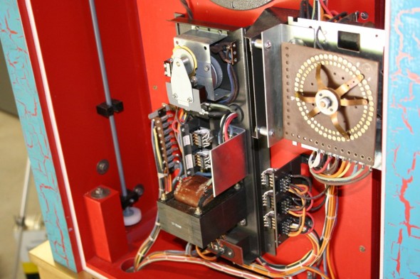
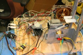
As mentioned earlier, this would have been a tremendously easy series of tasks to perform with a PIC, Stamp, Arduino, or any one of a number of other programmable microcontrollers. But not wanting to have any dependency on components that will be obsolete in a few years, I chose to perform these functions with a stepping switch from an old bowling machine, a motorized timer, and a series of relays. I was always short of circuits on the stepping switch, and at times while trying to figure out this simple mechanical logic I was feeling pretty thick headed, but in the end it all worked.
Since a microcontroller was required for control of the mp3 music player, I decided to add in some optional operator programmability functions. These allow control of the music and some play stimulator functions, one of which scares the bejesus out of me every time I have to work on the machine. More on this later.
Design and Construction of Key Elements
Cabinet
The choice of cabinet material was driven in part by the open structure of the upper cabinet. The windows on either side of the figure actually needed to be functional as doors to permit maintenance access, and as such they would offer no structural strength to the upper cabinet box. It was also very important that the structurally weak doors be made of a material that would not warp after assembly. The door/window frames and cabinet panels in most cases would have their edges routed and finished, which precluded the use of any plywoods. For these reasons a commercial grade of medium density fiberboard (MDF) was chosen for a good portion of the cabinet construction. This is not my favorite material to work with, and it needs to be sealed properly when finished, but it is very dense, it machines well, and it is very stable.
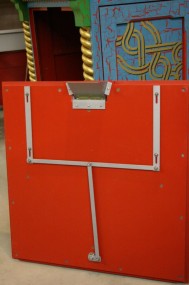
The inner structure of the upper cabinet is made of welded steel with 1″ MDF window frames attached to it. This frame was necessary to maintain the structural integrity of the upper cabinet without any help from the side door/windows. This adds to the weight, but the upper cabinet is as strong and as square with the side doors open as it is with them closed. The side doors each carry a sliding steel locking bar that pulls them tightly shut and latches them at both the bottom and top.
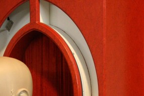
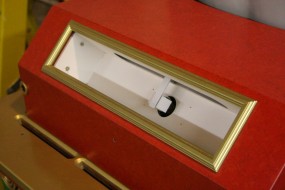
The front and side window frames used rail and stile construction throughout but with an added embellishment. The basic frames were simple enough rectangles, but the ovals that encircle the view of the figure’s head were separate pieces that had the left and right ends routed with the rail router bits in order to fit inside the frame. On top of that, the unique design of the pointed details at the base of the ovals required extra work. The routed right-angle inside corners would be radiused if routed as a single piece cut to shape. The sharp corners required that parts of these decorations be made in separate pieces, routed, and then glued together. The time spent making the doors was the main factor which influenced the decision to abandon plans of building two identical machines at the same time.
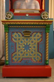
The lower cabinet panels were somewhat easier to make, but because of the ornate painted pattern each panel assembly needed to be made in two parts: the flat panel, which would be painted and stenciled, and a separate rail and stile frame that would be painted separately and attached later. The lower cabinet sides were actually split vertically in the middle with another stile, and later the stencil pattern would have to be split to allow for that extra width.
The cap that covers the upper cabinet and serves as a base for the dome was made of solid wood and plywood. The base for the lower cabinet needed to be very structural and was made from solid maple (from one of my own trees) with a good amount of internal structure to accommodate leveling feet and moving dollies. At this point I didn’t know how structural it needed to be and as it turned out it was a good thing that it was overbuilt.
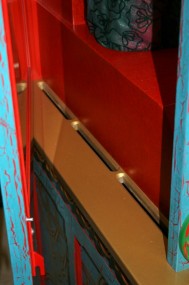
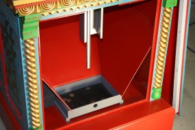
Most of the cabinet work was straightforward but some was more complex and unconventional. Coins that missed the figure’s mouth would be flying all over the inside of the cabinet. Some of these would accumulate on the table in front of Zoltar (as seen in the film), but others needed to have a path to a collection hopper in the lower base. The cabinet had to be designed to allow coins that fell around Zoltar’s table or his upper torso to have clear access to the hopper in the lower cabinet. Slots were routed all around the table, and the torso was openly suspended on its base such that coins that hit the shirt would simply slide straight down to the floor of the cabinet. There would always be a few errant coins, but this design has worked quite well considering.
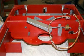
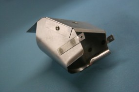
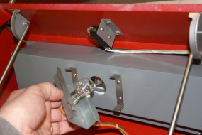
The column behind the figure and the table in front both needed to have lighted annunciator panels with separate light boxes built behind them. All of the light boxes had suspended metal deflectors placed between the bulbs and the panels to eliminate hot spots and provide uniform panel lighting.
Some of the light panel openings as well as the door frames and other precise routing jobs required a fair amount of time to be spent on the task of making custom routing templates and jigs. The routing itself usually went very quickly, but the jigs took hours to make.
The majority of the wood cabinet would consist of six parts stacked and bolted together: the base, lower cabinet, main table (the gold one), upper cabinet (Zoltar’s house), and the cap. There were several other trim pieces and the dome that would add to the overall assembly. It was essential to make the entire machine break down into manageable pieces in order to fit through doors and to be able to carry them (the finished machine weighs over 650lbs).
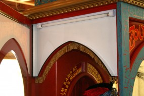
One of Three Separate Light Boxes for Illuminated Panels – These Had to be Added Very Late in the Design
Cabinet Trim Elements
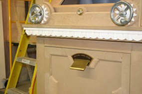
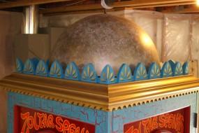
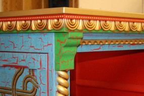
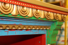
The one single piece of cabinet trim that I was able to simply go out and purchase was the wide border used for the roof cap (gold in the pictures). This was a standard wide cove molding used upside down and mitered at the corners. I was unable to see very much of the design used on the original machine, but I had the impression that it was something like this. An extra maple trim piece mounted underneath the cove on three sides was scalloped at regular intervals with a large-radius cove router bit.
A horizontal trim that mounts above the card ejection slot on the lower cabinet hides assembly bolts and was made using this same scalloped trim pattern. It was built up of various pieces of wood and routed strips.
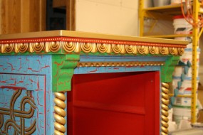
Close-up of Trim Details – These Are Best Guesses and Are Probably Quite Different from the Original Prop
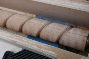
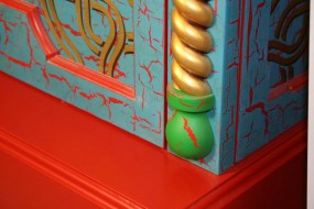
The vertical spirals on either side of the lower cabinet were also custom made. Spiral wood twisted-rope turnings are available commercially but I couldn’t seem to find the correct pitch or look. My past experience with machine-made spirals is that they can sometimes be inconsistent, so I decided to make these too.
A single-use spiral turning jig was made that rotates the spindle blank as it slides along the fence of the router table. This required a cable system that connected to the fence and was guided by small nylon pulleys to a flanged hub on the end of the spindle blank. This hub diameter was somewhat critical to obtain the correct spindle rotation per linear distance moved and hence the correct pitch for the wood spiral.
A large-radius round-over router bit was ground to remove the pilot and to extend the cutting radius to a cutting point in order to create the crevices between the ropes. The spindle blank was made of two alder strips lightly glued together with a paper separator. The ends of the blank were drilled with a lathe centering bit right on the end of the glue joint; this way the finished spiral could be easily split into two halves without losing any width due to a saw kerf.
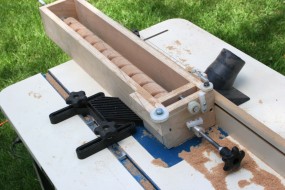
Hastily Created Jig For Routing Spiral Trim Patterns. The Wood Blank Rotates as the Jig Slides Along Fence
The wood half-spirals were finished and primed, but in the end I chose to cast them rather than use the wood pieces. One original was used to make a silicone mold and two identical spirals were cast from gel-coated resin.
Both of the trim pieces above and below the spirals were best-guess designs made from wood and cast similarly in resin.
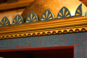
I Received Some Criticism for the Simplistic Pointed Trims. I was Trying to Copy the Original, Even if it Looked a Bit Cheesy
The pointed flat-wood castellations that surround the dome on the cap seemed a little simplistic when viewed the context of the other rather ornate cabinet trims, but I had reason to believe that this is how the original machine was decorated. It certainly would have been no real added effort to design and cast trim pieces with a more three dimensional sculpted look, but I was trying to copy the original and not add my own interpretations along the way (although this was at times unavoidable). This detail was criticized by a local arcade machine collector when I first put the machine out on display, but I think he missed the overall picture of what I was trying to do.
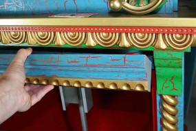
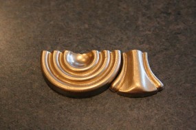
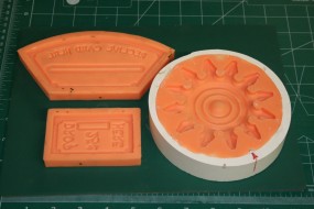
The bunting-style trim strips under the main table at the top of the lower cabinet (gold with red trim in the pictures) were also cast in resin. The original pattern was made from a wood disk grooved on a lathe and cut slightly over half size. The bell-shaped flared filler piece beside it was carved in basswood. A mold was made of both parts, and they were repeatedly cast in plaster to replicate enough parts to assemble a full length pattern. A long dimpled trim strip was added to the top, and a silicone mold was then made from this assembly. The size of the original parts was critical so that the corner miter cuts on the front and side trims (which were different lengths) would occur at the end of one of the circular patterns and not in the middle.
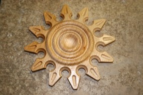
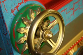
The round decorations located behind the hand cranks also appear in another location during some but not all scenes in the film. In some camera shots they are visible on the left and right of the front window at about the same height as where the coin ramp attaches to the inside corner of the cabinet. They appear to be mounted inside the glass, and they also look out of place to me. I’ve wondered if they were temporarily placed there to conceal some internal lights for a particular shot or if they were hiding something else. In any event I left them off because they just don’t look like part of the design (and they are missing in some shots anyway).
These trims were cast from resin using a mold made from the original maple pattern shown. The original maple pattern was made on a manual milling machine equipped with an index head.
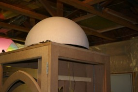
The top dome can be considered part of the cabinet trim as well, and making one out of fiberglass was not a huge job. An inflatable exercise ball of the correct size was used as a pattern. It was sprayed with a PVA mold release coating to act as a solvent buffer and then painted with black polyester tooling gel-coat. This was then layered with resin and fiberglass cloth. When cured this became the female mold from which the male dome was cast. The exercise ball’s ridges were easily sanded off the final molded part.
Unfortunately I miscalculated the size of the first dome by quite a bit, so the entire process had to be repeated. This required inflating the ball well beyond its stated dimension to make the new mold, but it survived without any problem.
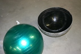
Fiberglass Dome Mold Made Using Exercise Ball Inflated to Correct Size – Ridges Easily Sanded Off Final Casting
Head/Neck Mechanism
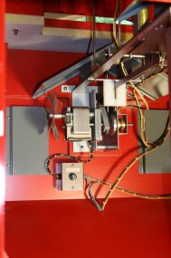
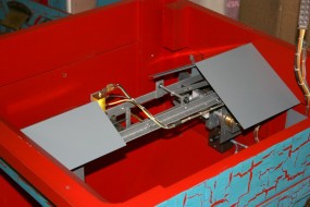
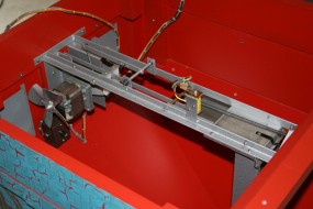
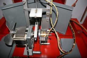
It wasn’t difficult to figure out the required gear motor speed by counting the number of head movements in a minute. I found an AC shaded-pole gear motor that fit the bill.
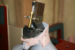
The large size of the motor dictated that it had to be mounted in the lower cabinet, and potential flexibility in the long linkage was a concern from the beginning. I dislike mechanical motions that are jerky or have backlash, and it was important to make the head motion as smooth as possible. Moreover, the head rotation axis had to be slightly behind the center of the neck, with a single push rod linkage behind that, allowing at best a very short moment arm. The head and mount are lightweight but nevertheless the force to rotate them with a short arm would be high. A dual push-pull rod system would have been better, but the mouth and chin area had to be kept clear to funnel coins down through the torso. A single push rod (pull rod, actually) is always in tension due to the weight of the head so no spring was needed.
It would be essential to have a rigid push rod and slop-free end linkages, but it was equally important to ensure that the distance between the neck pivot and motor was absolutely fixed and rigid. The neck and torso casting – further reinforced internally with full length tube for a coin chute – was very rigid by itself. To maintain this rigidity to the motor allowance had to be made to accommodate adjustable threaded steel rods between the torso platform and the motor mount.. I also machined a brass hydraulic dampener (a metered piston/cylinder filled with oil) that mounted on the head linkage to further prevent any chance of the bounce, but it put some additional load on the motor and in the end was not necessary. The head rocks perfectly smoothly, but if space had allowed it I would have used a longer lever arm.
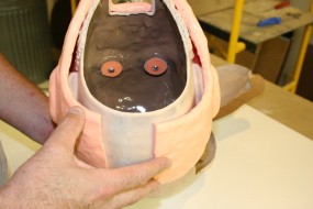
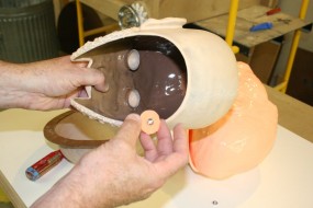
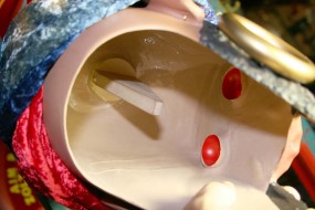
The head casting is hollow and mounts to the linkage with a simple tapered wood plug and socket. This allows the head to be removed simply by lifting it up, but more importantly it also positions the head very precisely when fully seated. The fit between the stationary and moving parts of the mouth must have very close clearances to prevent quarters from jamming in the gaps, and this male-female connection works very well. The lights for the eyes stay with the neck mechanism so that the head casting can be removed without fussing with wires.
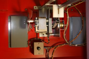
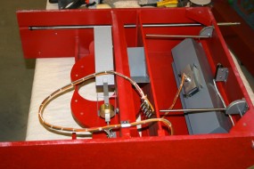
Head-Rocking Mechanism Mounted to Back of Lower Cabinet. The Gray Covers Block Access to Interior Through Vents
Eyes
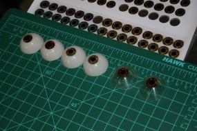
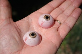
The eyes had to be translucent to allow for backlighting, and I took a few liberties here because I couldn’t really tell exactly what the original machine’s eyes looked like. Among the various film and DVD Extras scenes they sometimes look white and sometimes red under external lighting, although they were always red under backlight. I kept it simple and made normal white eyes that would illuminate red under backlight.
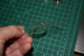
Polycarbonate half-spheres were vacuum formed over a correctly-sized steel ball and then cut from the backing sheet. For the iris I found some magnified photos of a human iris and modified the colors in Photoshop. These were printed on thin paper using archival ink and cut out using a rotary cutting tube of the correct diameter. Each iris was saturated under vacuum in water-clear resin (to prevent later bubbling) and then potted into the front of each transparent shell. The resin was allowed to cure in a 60psi pressure pot to further minimize the chance of bubbles.
Once the resin was cured the eyes were airbrushed internally with a translucent off-white tinted acrylic paint. Just for fun I scratched some blood vessels into the white before over-painting the white with a translucent red. The eyes look normal when illuminated from the front, but a white backlight will make the eyes glow red. Using a red light bulb creates a different look, and I like the white backlight better.
I made about a dozen eyes at one time to try different colors and to make spares – they are quick to make and they don’t look bad when used in a head that is not really intended to be realistic.
Card Ejection Mechanism
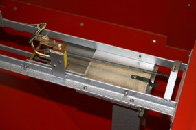
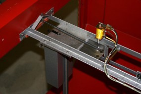
Finding a reliable mechanism for dispensing a business card was more difficult. I did not want anything that used rubber friction pads (remember 100 years from now…) to grip and push the cards. After some experimentation I ended up making the entire card ejector, which was in keeping with my tendency to go custom rather than adapt something that would look out of place. The ejector was based on the design used for coin payout slides in mechanical slot machines: a stack of cards is held under pressure against a sliding plate, and when the plate slides it skims one card off the top of the stack. This design required some tight tolerances to slice off one .010″ thick card – no less, and no more. It does work very reliably but it is intolerant of cards with any dog ears or wrinkles. Any cards recycled through the ejector need to be checked and weeded out if necessary.
A solenoid releases the sliding spring-loaded plate that pushes a single card from the stack. A hook attached to the ejection plate drops down when the plate slides forward. Once dropped, the hook lies in the path of a roller on the end of the head-rocking motor arm. On the next revolution the roller catches the hook and pulls the plate back to the loaded position.
This plate can be seen ejecting a card and being reloaded at 1:12 to 1:16 in the second video included with this article.
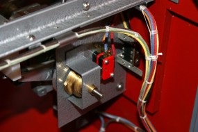
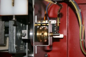
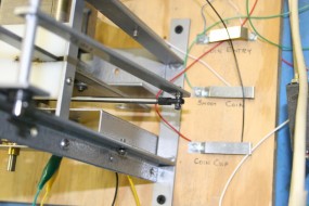
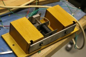
There would also be a need to sense certain positions of the motor cycle, one of which was for timing the coin release to hit an open mouth as described earlier. Two brass cams mounted on a shaft driven by the head motor are used to activate two micro switches for this purpose.
The Coin Ramp
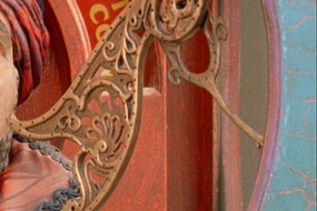
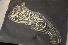
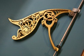
The ornate casting used for the original coin ramp looks like it came from some other antique, perhaps a kerosene lamp holder or something similar. It is not the optimum shape for the requirements of the coin ramp, and it looks adapted, but I never found anything similar. Even my friend Kevin who has bought and sold antiques all of his life was certain that it looked familiar but was unable to pinpoint exactly what it was.
The original looked like a piece cast from a carved pattern, with the filigree defined in multiple depths. Some of the curves are oddly irregular and less than smooth, so there is a chance that it was created specifically for the original prop. I may never know.
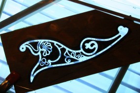
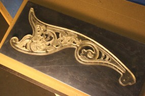
This part was recreated using a photopolymer process similar to that used to produce printing plates and detailed rubber stamps. The original pattern was replicated, defects and all, in Adobe Illustrator by examining views from various angles captured from the film. From this file a negative was created by printing the inverse image on a transparency film. A layer of liquid photopolymer pattern resin was sandwiched between two glass plates, and the resin was exposed to UV light on both the back and front sides. The resin cures into solid plastic wherever it is exposed to UV light. The back side is fully exposed first to form a solid backing plate of plastic. The partially cured glass/resin assembly is then flipped over and the top (uncured resin side) is then exposed to UV through the filigree artwork. This cures the raised portions of the filigree onto the previously cured backing. The exposed part is then removed from between the sheets of glass and the uncured resin is washed away. This results in a part with a raised surface level and a background level.
This photopolymer process will be discussed separately in a future article. It serves as a low-cost alternative to CNC milling for producing plaque-like patterns.
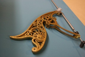
The part produced by the above process represents a single side of the coin ramp; an exact opposite part was produced by the same method for the other side. The two parts could have been bonded back-to-back to make a pattern, but I chose to bond them to an aluminum match plate for rigidity. From this matchplate a silicone mold was made, and the final ramp was cast in brass-loaded urethane resin. A solid brass part would have been too heavy for the steering mechanism to manipulate.
The coin guide was created using a bearing-guided slotting router bit to cut a deep groove along the curve. The appearance of the coin ramp is a little different from the original in that it is a two-level relief pattern rather than the continuous-depth relief of the original, but the effect is still quite good.
Coin Entry and Card Award Plates
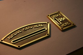
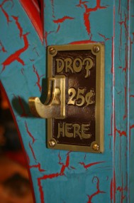
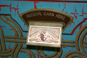
The artwork for these plates was also created in Illustrator, although the font had to be hand-drawn. By the time I made these plates, the film DVD had been released and the extras included on the disc showed a close-up of one of the plates. I would never have guessed that such an unusual font was used for the raised lettering, and hours of scouring lists of available fonts came up with nothing, so I simply drew those letters that were needed for the two plates. I was very happy with the results.
The patterns for these plates were created using the same photopolymer process described above and silicone molds were again used. The only difference in the final castings was that the brass powder content used in the brown-tinted urethane resin was very high, and the finished parts could be sanded and polished almost like solid brass castings. The effect and the match was very good, although had it been summer I probably would have simply cast the parts in solid brass. Brass powder at the time was more than $17 per pound, and that was well before metal speculators drove copper prices through the roof.
The Coin Entry
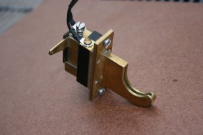
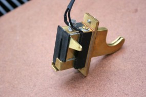
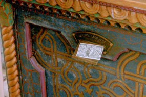
Given the appearance and size constraints of the coin entry, this component too would be designed specifically for the application. The coin ramp had to be pivoted nearly in the corner of the cabinet, and there was no room for a separate coin detection switch and a coin release mechanism. The entire assembly really needed to be contained within and confined to a cavity routed within the thickness of the front window frame.
I designed and fabricated the coin entry shown in the picture using solid brass, Delrin (acetal), and silver for the contact surfaces. The slot for the coin path was milled symmetrically into two plates that were then silver-soldered together (see the seam line) and the final hook shape machined from this assembly. The contacts that sense the coin are also used to physically hold it back and release it. The control horn on the top side is pulled upward to release the coin. This coin entry has worked very reliably and it releases the coin from nearly the same level at which the coin is inserted, which helps the coin attain sufficient speed and trajectory to reach the figure’s mouth.
Coin Ramp Steering Mechanism
This appears to be a fairly long and complicated control system, but it was necessarily complex to obtain smooth ramp control with a minimum of backlash without adding any unnecessary linkages that might be visible from the outside.
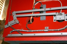
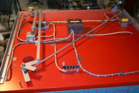
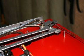
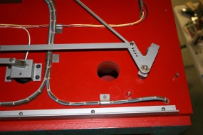
The coin ramp is supported in the front corner of the cabinet and rotated by a steel torque tube. Within this tube is a steel rod that moves vertically to raise and lower the coin ramp. Both of these movements are connected via push rods across the roof of the upper cabinet to the two rear corners where they connect to bellcranks. The bellcranks are locked to the upper ends of two long, solid steel torque rods that run vertically along either side of the rear of the upper cabinet.
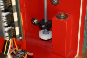
Two nylon worm gears at the lower rear of the upper cabinet rotate these torque rods through adjustable friction clutches. The clutches provide sufficient friction to move the ramp to all positions but they will slip when the limits of ramp motion are reached, thereby preventing any chance of damage to the mechanism.
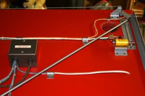
The nylon worm gears themselves are driven by the long shafts that run horizontally on either side on Zoltar’s table and are driven by the hand cranks. The rear ends of these shafts are cut with either right- or left-handed worms to provide the correct intuitive ramp motion for the handle rotation. The left crank controls left-right ramp motion, and the right crank provides up-down motion. The result is a very intuitive response and great sensitivity to motion.
This design is almost totally free of backlash or slop. It is really remarkable, given all of the linkages in the path, that the ramp responds subtly and immediately to hand crank movement. Great attention was paid to preloading linkages and making the worm gear self-compensating for wear in order to achieve this tight motion. I am extremely happy with this portion of the design.
As mentioned early in this article, a gear motor in the roof of the upper cabinet resets the position of the ramp after a winning play. A crank on the gear motor shaft links to the ramp-steering vertical torque rods at the rear of the upper cabinet. When the motor is activated, it cycles through a complete revolution and sweeps both torque rods to their respective end-stops, overriding the clutches that couple the hand crank motion to the torque rods.
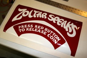
The top three Zoltar Speaks illuminated panels use three colors but the three annunciator panels on the column and Zoltar’s table use only two. In the past I would have screen printed artwork for the various colors onto the back of clear glass or acrylic as a more traditional method, but I had to rethink this.
When weighed against the prospects of future peeling and fading screen printing, not to mention the cost and hassle of artwork and screen production, the use of vinyl on acrylic sheet looked better all the time. Any evidence of the layers of vinyl adhered to the white acrylic diffuser panels would be nearly hidden by a second transparent acrylic panel on top of the graphic panel. This would also provide a layer of acrylic on either side of the vinyl to protect it from UV fading caused by either the internal or external fluorescent lights or the sun. The use of vinyl graphics was very easy to justify both for cost and more importantly for longevity.
Hardboard templates were made for all of the panels and 1/8″ cell-cast acrylic was routed to match. Each of the panels was completely covered in yellow translucent vinyl. The red (for the two-color panels) or red and orange graphics (for the three-color panels) were wet-applied on top of the yellow. The yellow base under the red or orange colors had no visible influence on those hues, and this allowed the artwork to be greatly simplified. I couldn’t have been happier with the results, and they only took about a day to make rather than multiple days.
Paint and Finish
One of the most distinctive features of the original prop in the film was the authentic appearance of its weathered crackle paint finish. If you study close-up stills you will appreciate just how well the finish was aged.
I have always had difficulty building something or performing a restoration and then distressing it. I love the appearance of the original machine in the film, but I stopped short of distressing the finish on the replica. It may get artificially aged at some point by me or some future owner may be more inclined to do it – but you can’t really go back if you don’t like the effect, unless I find a non-destructive way to do it.
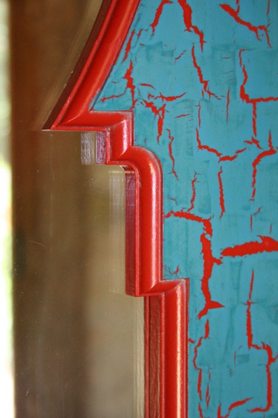
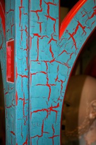
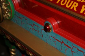
The basic finish on the majority of the machine consists of a heavy crackle finish with an vermillion red-orange base color showing through cracks in a teal topcoat. Some views of the original woodwork show the teal color that I used, but some appear darker and more green. It can’t matter now – the crackle finish can’t be repainted to a different color without going through the whole crackle process again. Not in this lifetime. Some other trim pieces do have a distinctly green color as I have used.
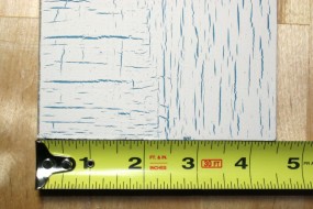
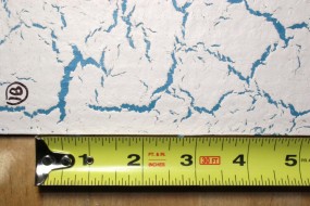
The crackle paint finish is easy to achieve but hard to control. It is easy to get a finish to form cracks, but it is difficult to produce a consistent appearance over a large area. Whether cracks appear to be large or small or randomly oriented or linear depends heavily on the application technique. Accomplishing a uniform overall appearance with a crackle finish requires a fair amount of practice on sample pieces to ensure that you are in a flatter part of the learning curve before the real painting begins.
Crackle paint technique is a topic worthy of a separate article. Many tutorials and videos that will give the basic techniques may be found on the net, but a series of experiments that I ran recently using inexpensive white glue as a crackle medium demonstrated the wide range of finishes that can be achieved using different application methods, and I want to document these for my own future reference if nothing else.
For preparation all of the edges of the MDF cabinet material were deeply sealed with a fast-dry sanding sealer until they were approximately as absorbent as the smoother surface of the stock. All sides of the MDF were then sealed with BIN shellac-based tinted primer, which has become a favorite primer. It dries fairly quickly, but after a full day it becomes very sandable. I had previously used Kondar lacquer-based automotive primer, but the BIN shellac is less expensive and is very tenacious.
Once the MDF was thoroughly sealed and sanded, the fuzzy edges became strengthened and non-porous. An eggshell flat vermillion base coat was applied to all surfaces that required it and allowed to dry.
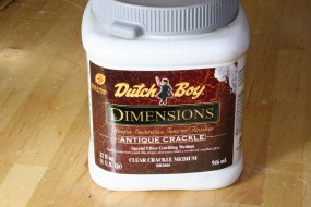
For this project, a commercially available (at the time) Dutch Boy crackle finish medium was used. This crackle medium appears to be an animal glue type of material that dries on its own but easily liquefies when overcoated with fresh paint. It could be brushed or rolled on, but I found that the application method of both this medium and the color topcoat could have an effect on the crackle appearance, so I chose to roller-paint the medium as this tends to produce a more uniform film. This would leave the final crackle pattern dependent more on the method of topcoat application (which would be brushed) rather than the composite effect of two variables.
I found this crackle medium to be very difficult to use. The instructions indicated that the medium should be allowed to set for about an hour prior to applying the topcoat, but I found this to be too short. When the flat teal topcoat was applied it would start cracking and separating into islands almost immediately, preventing any chance of a second brushing to smooth out the topcoat. As soon as the topcoat hit the crackle medium, the medium liquefied and any subsequent brushing would just make a mess. Even after 24 hours of drying time for the crackle medium there would be very little time between the application of the topcoat and the onset of the crackling. It was a race, as if you were trying to run on thin ice while watching it disintegrate right behind you.
Even if this need for rapid application of the topcoat could be handled for narrow items like the window frames, there was a more insurmountable problem with trying to cover large areas such as panels. The normal brushing technique to cover a large panel would not work. You would always have to try to blend the new paint with a previously painted area that could no longer be touched, otherwise the previously-painted, floating top color would tear and not blend properly.
I tried spraying the top color finish, but the cracking pattern relied heavily on thick and thin streaks in the top coat such as you normally get with brushing; the thin areas tended to be the weak lines where cracks began, and the thick areas coalesced and held together. A sprayed topcoat was very uniform and although it did crack, the pattern was different and was not the look that was needed.
Eventually I settled on a slow but predictable process that gave consistent results. The crackle medium was rolled on and allowed to dry overnight. The topcoat was a flat latex (flat cracks better) used full strength and applied with a one-inch brush. The topcoat paint was not really brushed on, however. The brush would be loaded and the paint plopped onto the surface with the brush held flat, applying a square of heavy paint not much more than 1 1/4 inches on a side. Any follow up brushing of this blob of paint would only be done if necessary to dabble up a thick edge or to square it up. This would be repeated in long lines, reloading the brush each time and alternating the orientation of the brush 90 degrees with each square. The next long line of squares would be alternated from the first resulting in a basketweave pattern over the entire surface. Since you weren’t really brushing the paint on nor pulling on previously painted areas, it was easy to seamlessly join the newly painted sections to the soft, previously painted areas.
The combination of a thick paint application and the alternating brush orientations resulted in a bold crackle pattern with dominant horizontal and vertical cracks and a nicely textured, almost lumpy finish. The downside was that the all surfaces of the entire machine had to be painted with this slow method, one square at a time. Nevertheless, slow and in control is better than fast and random with the risk of having to strip the paint and start over.
Since the cracked areas revealed vermillion with the crackle medium exposed, it would have been terribly sensitive to moisture if left this way. The cracks needed to be sealed, but any sealer that protected the cracks would also destroy the nice flat, weathered look of the teal top coat.
I found another slow but reliable method to achieve the right look. The entire surface was sealed with the flattest clear finish that I could find, which was still a bit shiny. After the clear was dry the entire surface was sanded with a foam sanding block (like those used for sanding drywall joints). This cut through the clear finish on the surface teal but didn’t touch the recessed vermillion cracks. The top coat was thick enough to absorb this sanding, and the roughness of the “plopped on” teal paint helped created a nice variation in the finish after sanding. The final teal topcoat was mostly flat but with an occasional bit of darker sheen that made it look like a randomly weathered and chalked finished.
The final crackle finish seen in the pictures is the result of some controlled experimentation combined with a whole lot of accidental luck.
Any other base paint on the machine was applied conventionally, the only exceptions being the dome which was rag-painted with several tones, and Zoltar’s red table and backdrop which were painted and textured with a sea sponge.
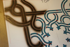
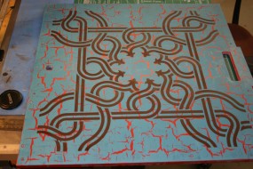
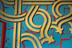
First Coat of Pattern Was Dark to Give a Shadow Appearance. Hand-Cut Stencil Was Shifted Horizontally and the Highlight Gold Sprayed On Top
The shadowed gold filigree on the lower cabinet panels was drawn in Adobe Illustrator. I planned to use a vinyl cutter to cut the stencil but it was too large for my Stika cutter, so I ended up spending about four hours manually cutting the stencil out of card stock.
The front panel was painted first, then the stencil was cut in half vertically so that the sides could be stenciled; the middle vertical stile required that the pattern be split. The rail and stile frames for the panels were removed so that the stenciling could be performed on a totally flat surface.
In each case the stencil was first offset a little from center and a dark brown color was sprayed on to represent a shadow. When that was dry the stencil was then perfectly centered and the gold sprayed on, leaving the gold filigree with a shadow that was offset both horizontally and vertically. This really was a stunning addition to the crackled panels, and it demonstrated how effective a good paint design can be.
After the pattern was dry the rail and stile frames were screwed onto the flat side and front panels from behind.
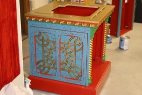
Sides Used the Same Stencil as the Front Except it was Painted With a Center Gap to Account for Center Stiles
Electromechanical Functions
This part of the design was a humbling experience. I could have programmed a microcontroller to perform all the required functions in one-tenth the time that it took me to accomplish the same task with an electric timer, five relays, and an electromechanical stepper switch. To be fair, even this very simple machine has more going on inside than first appears, but still…. It was easy to design the circuit to a point, but then I started running out of contacts on the relays or the stepper. I was at times brought to my knees by something so simple that would have made any competent pinball machine designer in the 1960s laugh. Fortunately the solenoids used for releasing the card and the coin had their own integral contacts that gave a few more options and helped bring everything together.
The one-minute timer forces the gameplay to stay on schedule, and at certain times the players needs to interact (as directed by the annunciators) or the game will simply time out. In particular when the time comes for the user to press the button to release the coin, there is a limited window in which the machine can time the release to hit the mouth at its widest opening. If the player is still fidgeting with aim at this time, the window may be missed.
Nothing is critical and gameplay is very natural if you are paying attention and following directions. But I have learned that you need to plan for all contingencies so that machines don’t get hung up in some weird state due to incorrect or poorly timed player inputs. Implementing fail-safe modes for these errors generally requires more circuitry than it takes to simply perform the basic functions.
And again this is a very simple machine compared to electromechanical pinball and arcade games.
Sound and Microcontroller Module
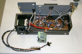
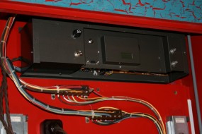
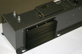
This is the Optional Sound/Music Module and Microcontroller; The Machine Functions (Quietly) Without It.
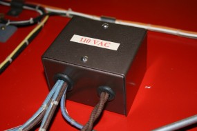
Since both of these functions require electronics and I wanted any electronics to be optional and hidden, they were combined into one modular enclosure. This metal enclosure mounts in the upper rear of the upper cabinet and can be removed in less than five minutes. Removing it does not affect the basic operation of the machine.
The audio portion of the module consists of an MP3 player, a stereo audio amplifier, and a power supply. The MP3 player is a modified portable player that requires the usual series of sequential button presses to start play, sequence to the next tune, etc. On top of that, the normal operation mode for the player is to shut off automatically if it is not playing music, which would not work for a fortune teller that needs to have the music begin as soon as a coin is inserted.
Fortunately all of the required signal sequences to trigger play and keep the player awake during idle times could be easily generated by a microcontroller. I had several options here, although I chose to use a Parallax Basic Stamp II because I had several of them and they were very easy to program interactively. My intention was to write all the code on the Stamp and then make the necessary conversions to program a PIC microcontroller and make a dedicated PC board, but I never went that far. The Stamp worked fine and it would have just been more busy work to convert it.
One unfortunate design flaw in the particular MP3 player that I used forced a change to my music plans. The fortune teller has a speaker in the rear of the lower cabinet and one behind Zoltar’s head inside the windowed upper cabinet. I had created the midi music files to play on the rear channel with the breathing sound coming from the other channel behind his head.
Unfortunately, the player appeared to have a design flaw and it would occasionally swap the left and right channels of the MP3 file – breathing would come out of the back speaker and the music would come from the inside speaker, which was heavily muted behind the windows. Nothing could be done at this point except embed the breathing into the music and play the same audio through both speakers.
Since the MP3 player controls did not require much program space on the Stamp processor, I added some other fun but unnecessary functionality. These functions are all accessible from the front coin-release push button by pressing an entry sequence and listening to tone and eye-flash responses for acknowledgement. These functions include:
Software control of music volume. Hardware volume controls are in back.
Selection of first music file in sequence. I just keep it on the “big” theme music.
Play Stimulator Mode. This randomly flashes the eyes and makes the electrical buzzing sound when the machine is sitting idle (see the start of the videos) in order to draw attention. It also startles people that might be looking at the idle machine at the right time. But mostly it just makes me jump out of my skin when it goes off while I am inside the machine doing some maintenance. I always forget to disable it. Every friggin’ time…
Play Delay Mode. This actually makes the machine do nothing when the coin is inserted until you pound on the front (as Josh did in the film). The processor counts pulses created by pounding on the front after the coin is entered (which bounces the coin on its contacts). When it does activate, it initiates the eye flash/buzz sequence a few times before the machine actually starts. I don’t keep this play mode active because, well, it encourages people to pound on the machine. Duh…
Music and Sound
The main Zoltar theme that plays in the first video was based on the movie music and was arranged in midi using Cakewalk Sonar and several soft-synthesizer instruments. The music has to be timed to run for exactly one minute. Another theme loaded on the machine and heard in the second video above is called Sultan and was created the same way. I had grand plans to come up with a few more, but everything else sounded like music from Gladiator overlaid with the drum from the rowing scene of Ben-Hur. Making music is hard.
The breathing sound that becomes tiresome after the first thirty seconds was made by breathing into a RODE NT1A microphone, just in case you want to copy it.
Costume
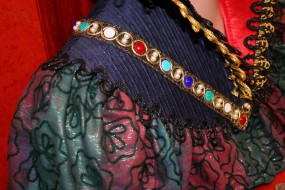
I searched to both ends of the internets looking for a good match for the shirt fabric and then I resorted to searching locally. The closest match that could be found was what can be seen in the pictures. It wasn’t like the original but I liked it and should have picked up a little more. Most of the other fabrics were easy to find velvets, pannes, and wide corduroy.
I didn’t know this when I started out but I would eventually have to learn to sew to make the costume. Becky gave me a sewing machine 101 lesson and I’ll admit that it was fun and something I’ll do again on the next figure. It’s really not much different from cutting sheet metal and spot-welding, except everything is squishier. Like sculpting I’ve learned to appreciate the skill necessary to do it well.
On a side note, after struggling with a contemporary crap-o-matic sewing machine we went retro and bought a couple of the old classic Singer Slant-O-Matics (one is the bizarre but cool Rocketeer model). These are awesome machines even 60 years later. They are built like machines should be built and their longevity is a testament to something that has been lost. When someone says that their _______ runs like a sewing machine, this is what they are referring to. But I digress……
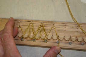
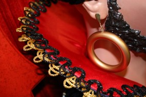
The gold and black loopy cord trims were preformed in the wood jig shown and fixed with a little glue to hold their shape until they could be stitched into place. These look pretty good, although a better cord could have been found.
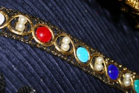
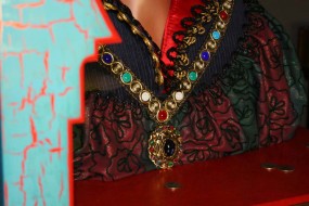
The gold necklace band was actually a decent match – this trim was available in a variety of styles and the one selected was quite close to the original. It was embellished with pearls and colored glass lampwork cabochons that Becky made.
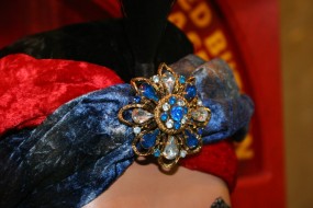
The necklace pendant and the turban ornament are vintage items bought on eBay.
Miscellaneous Details
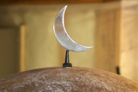
The top dome is supported on multiple stepped blocks so that it is open underneath, allowing sound to pass from a chime that is mounted on the cap. The chime rings with every change of the illuminated annunciator panels. A single threaded rod with a nut on top holds the dome in place. This nut has a swiveling crescent moon for a little extra ornamentation.
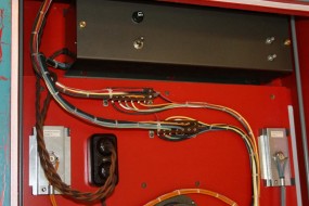
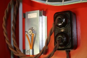
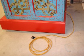
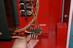
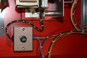
Cloth insulated wire was commonly used on old machines for line cords and internal wiring, and fortunately some types are being reproduced, The reproduction hookup wire tends to be quite large in diameter for a given wire gauge because there is an extra plastic insulation under the cloth (possibly for UL approval), but it still looks very nice when bound into a harness. The twisted gold wire for the power cord was perfect.
The artwork for the fortune card was redrawn in Adobe Illustrator and printed on standard two-side business cards. As mentioned earlier the card ejector was designed to work with a specific thickness of card, and smooth stock feeds better than a textured finish. The cards were printed with the “Your Wish Is Granted” message on the back side, which really doesn’t make this machine much of a fortune teller. Sometime I’ll printed up some cards with alternate messages and throw them in the stack. Having a few special cards might be good for a promotion or an event.
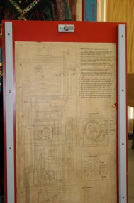
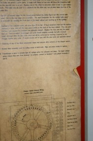
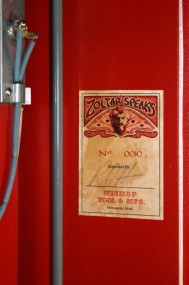
A fairly long operation and maintenance manual was written to document the circuits schematics, operation, programmability, and assembly and maintenance. It isn’t obvious how the various subassemblies bolt together, and even the steps to replace something like the front glass are easy to forget. In keeping with the vintage look, a large printed wiring diagram was given an antique finish and attached to the inside of the back door and a phony inspection and serial number label was attached to the inside wall of the cabinet.
The red button on the lower front window frame was made from brass and dyed anodized aluminum to look like the original. In order to prevent any extra wiring in that area the button is mechanical only; the backside has a steel pin that goes through a hole to press a switch inside of Zoltar’s table.
The machine has been on display at Kilroy’s in Minneapolis for a few years now ( I originally thought it would be there for a couple of weeks) but the thought of bringing it home to do a little work on it just makes my back ache. I has been amazingly reliable in its time there but a few things really should be done:
- Compose some new music themes (doesn’t need to come home for that)
- Add a Coin Entry Lockout – For reasons unknown, people like to stuff extra coins in it while it is still playing. It’s not a pinball machine, and it doesn’t give credits, but I probably should have anticipated that this would happen. This is a complicated task now and one that I can’t do on location.
- Possibly Make a New Head – I can now Google better pictures of the original face than I had to work with at the time, plus I have HD formats to study. This is unlikely because I am fairly uninterested in touching the machine these days, but you never know…
- It would be nice to use LED replacements for some of the incandescent bulbs just so I won’t have to replace them anymore. I would only do this if sockets were compatible so that it could still return to the original incandescents at any time.
Comments, Inquiries, Requests, Hate Mail, Fame, and Notoriety
One thing that I never really expected after finishing the machine and posting the video was the wide and wild range of comments and inquiries that would come my way. I genuinely appreciate the comments that I receive and will always respond to inquiries unless they are too bizarre or I just can’t understand what is being asked.
Here are a few samples:
- Someone wanted to rent the machine out for a wedding reception. I get quite a few offers like this for events, but it’s not a Karaoke machine; it weighs 650lbs and it takes three people and a day to set it up.
- It’s not unusual to hear from people that are themselves interested in building something similar, and I usually try to be helpful with details or suggestions of how they might get started with a project that is realistic and within their abilities. But often these conversations end up with requests to buy castings or parts which I don’t sell. Seriously, if you are building one of these machines and the only thing holding you up is that red push button, you really deserve to treat yourself and buy your own lathe.
- A New York advertising agency with legitimate street cred expressed interest in using the machine for some type of ad campaign. Our negotiations never got far – just mentioning shipping costs and the need for some legal release (from Fox, not me) sent them scurrying.
- A “professional” film maker asked for my original video takes for use in some type of project he was planning, but he wouldn’t elaborate when pressed for information. I couldn’t really think of too many professional films that would need my grainy standard-definition video that was shot by two bumbling amateurs late one night. I suspect something nefarious.
- One time I received a call from the self-described owner of the one-and-only original prop from the film. I could tell that he was a serious collector of coin-op antiques including fortune tellers, but he wouldn’t identify himself (some collectors are like this). I played along to a point until I realized that he knew less about the original machine than I did, which was next to nothing. Unless I was speaking with Garry Marshall, I suspect phone trolling. Motive not known…
- A YouTuber sent a me a limited-time offer of $800 cash for the machine (that’s a little over a buck a pound!!). That might represent a down payment toward shipping, but there was no need to be mean – I thanked him and declined. There have been other more realistic offers, but I haven’t acted yet.
- Lately I’ve been targeted by multiple (I think) individuals that are convinced that fortune tellers (including my replica of a fake one) are demonic or satanic devices. Some of the vile and rambling religious screeds that I have received have been an abundant source of keywords for my ignore list, so even if the subject line of your email offer to buy is as tame as “Will Pay $100,000 Cash For Your Demon Machine”, please understand that I might miss it.
But as I said earlier most inquiries and comments are very much appreciated. Here are a few additional Zoltar-related appearances or anecdotes that show what kind of fame and fortune that spending a year building something in your basement might bring to you as well:
Zoltar T-Shirts on eBay
Some enterprising individual on eBay is selling “Zoltar: I Wish I Were Big” t-shirts that use an image found on the internet. The part I found humorous is that they didn’t even steal the correct picture of the real Zoltar – they used the YouTube image of my replica.
Card Artwork
Once my artwork for the Your Wish Is Granted card got out, it started popping up in various places, one of which is a little questionable. I’m flattered, but it’s not me you have to worry about on your for-profit venture…
MAKE: 21 Magazine Article
This short story about the Zoltar replica appeared on the final “Homebrew” page of issue 21 of Make: magazine. Make: is a quarterly publication that covers all kinds of interesting topics, and anyone can write for them (which is why the story is in there). Writing that article taught me why I should not do it for a living.
Note to Make: whoever jacked up the color on the picture needs to have a Photoshop intervention….
Academy of Motion Picture Arts and Sciences
In early 2013 I was contacted by a representative for the organization that among other things produces the annual Oscar award presentation. After ignoring the first two inquiries as a hoax, I was contacted through a more trusted source which led me to do a little research, and it turned out to be legitimate.
The request was to allow my replica to be exhibited at their “Oscars Outdoors” summer event where big was to be screened. They apparently had viewed the video and thought that having a working machine at the screening would be an attraction. But as cool as it might have been to display it at an event like that, logistically it would have been very difficult and I was reluctant. We had several discussions and I asked why they didn’t simply try to get the real one from the film, which was located in their neighborhood. Of course they were already working on that angle, and contacting me was probably more of a contingency plan. The last I heard from them they had obtained clearance to borrow and put the original on display. I don’t know if that ever happened or if plans were changed – when I later looked at the film lineup for the event big had either already shown or had been removed from the schedule.
It was still pretty nice to be asked, though.
Rye Playland
Also in mid 2013 I was contacted by the executive director for an organization that had just obtained a long-term lease for the old bathhouse at Rye Playland in New York, the setting for the famous final appearance of Zoltar in the film. Planning is underway to erect a children’s museum on the site and they wanted to have a working Zoltar Speaks machine in the museum. They were looking at several options, including possibly having one custom-built by the company that originally made the film prop.
Since there has been no follow-up I am assuming that they have found an alternate solution, but again the interest was flattering and this is exactly the type of setting in which I would like to see the machine eventually find a home.
Final Thoughts: Please Don’t Let Me Do This Again
This was a fun and educational project, but even if I trim out the wasted time I can still account for more than a year of full-time effort lost to it. And because of this I really do not want to attempt to make another replica of anything. A huge portion of the project time is spent struggling to figure out how something should be made to look like the original, and the results are usually less than satisfactory either due to lack of adequate information or lack of skill to convincingly pull it off. On top of that, when you’re all done the best accomplishment that you can lay claim to is that you have copied someone else’s work.
At least with original work there is usually no reference against which to compare your success or failure. It’s like an original musical performance compared to a cover of a popular tune; everyone knows when you blow the cover piece, but the original may have been meant to sound like that. I really need to spend more time trying to develop my own creations instead of wasting…
Oh wait, this is cool….
![]()
Go to the Gallery for These Images and a Few More

