A $20 Transistor – L/R/C ESR Tester
Displays Device Parameters and Lead Configuration
I don’t know how long these have been available, but they are pretty cool. These testers are all over eBay in various forms for around this price, give or take. After ordering this I found a different one for about $23 with a built-in ZIF socket, which would have been handy instead of the pin socket shown here. But that didn’t have the ultracool white-on-blue backlit display.
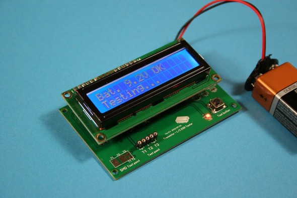
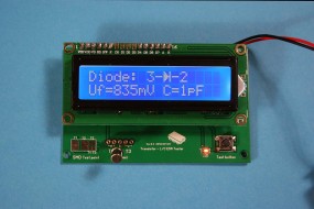
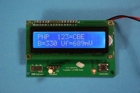
I am really surprised how well it works. It runs on a 9v battery. There are three available connection points (pins 1-2 are connected, as are pins 4-5 on the socket) marked T1, T2 and T3. For 2-terminal devices use any two connections, and for transistors use all three. You do not need to know diode or transistor lead configurations for the test – it finds them for you. SMD pads are available on the main board itself for testing surface mount components.
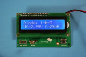
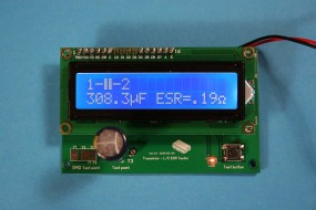
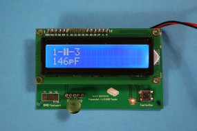
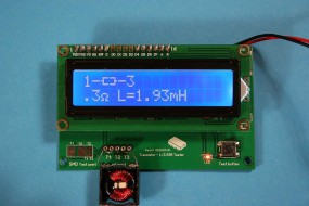
When a device is connected and the test button pressed, the display initially shows the battery voltage. After a short time the display will show a symbol of the component and the assignment of the pin numbers in accordance with the way you have the part connected. The display will also show the relevant parameters for the particular DUT.
Several capacitor values were measured and compared against a those taken on a dedicated capacitance meter, and in all cases the readings were very close to one another. I can’t verify capacitor ESR readings, so I’ll take what it tells me as the truth until proven otherwise. It is helpful not having to scrounge up a datasheet or use an ohmmeter to check those EBC versus ECB transistor lead configurations, too. I wasn’t even aware that it measured inductance (and series R) when I first got it. I saw the first picture on eBay and hit the Buy It Now without even reading that far into the description.
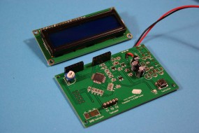
The assembly consists of the display board simply plugged into the processor board, with no substantial mechanical support beyond that provided by socketed header pins. It might be a good idea to put some standoffs on the larger board to act as legs, and figure out some way to keep the display from rocking on its row of header pins. Mounting the assembly in a case some Pomona clip leads and a ZIF socket would be handy too. Odds are that I’ll just use it as it is to allow easy access to the SMD pads.
![]()

