Restoration of a Berger “Chicago Ridge” Slot Machine
Reconstruction of an 1897 Berger Basket Case
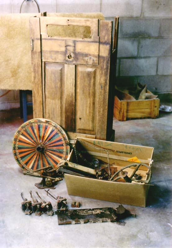
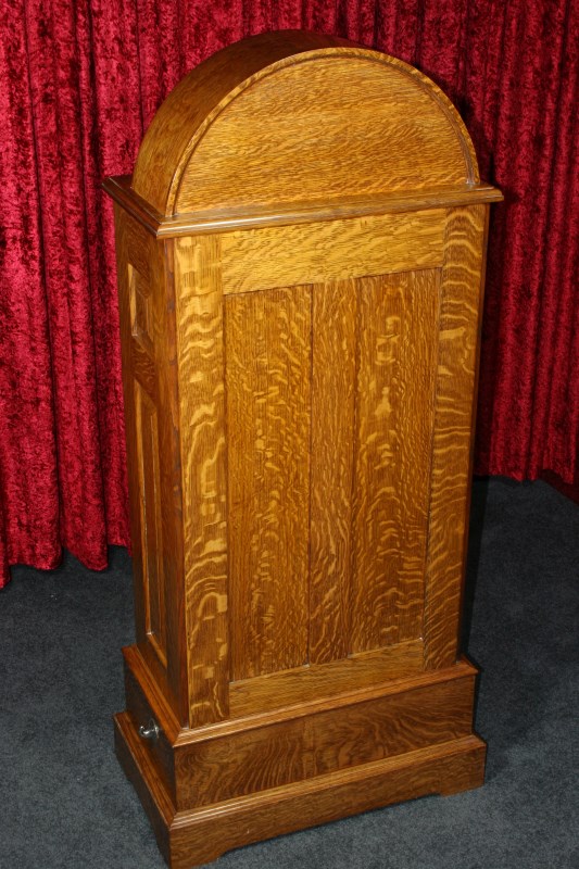
As Purchased
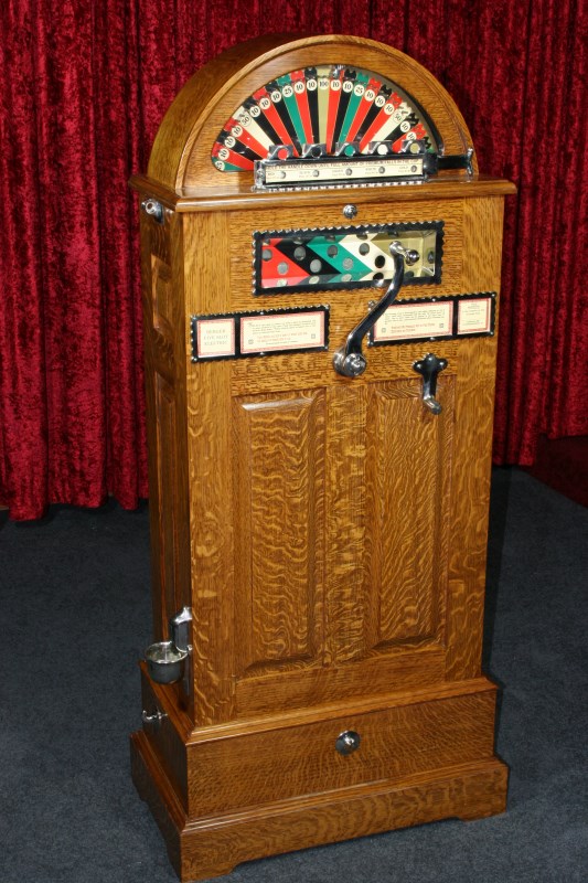
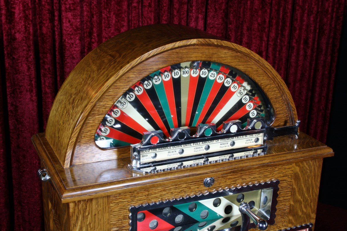
After Restoration
This was a fairly extensive restoration project that was completed in the mid 1980s. I had begun to write an article about it for one of the coin-op collector magazines of the time, but the magazine closed its doors before it was finished. I’ve probably forgotten a lot of details of the restoration, but that will help keep the story to a reasonable length. It was an interesting project because it went beyond the scope of a normal slot machine restoration and required the re-creation of many missing and broken parts. In the end it turned out to be a beautiful piece that is still part of my collection.
This restoration project predates digital photography, so the few pre-restoration pictures that I have were taken with a film camera and the prints scanned. The quality of the film images is poor, and I wish I had been more thoughtful about documenting things in the past. Thankfully I was able to retake all of the post-restoration photos (20 plus years later) with better lighting and a better camera.
I should note that the two framed cards above the handle appear to be some generic reprints and are probably not correct for this machine. I bought these at a Chicago show many years ago just as a placeholder and have never bothered to research to see if something better is available.
The Berger “Chicago Ridge” Upright Slot Machine
This machine was manufactured by the Paul E. Berger company at a factory in Chicago Ridge, Illinois around 1897. It is unusual in that it is an electric machine, operated from batteries, as opposed to the later and more common all-mechanical spring-powered upright slot machines of the early 1900s.
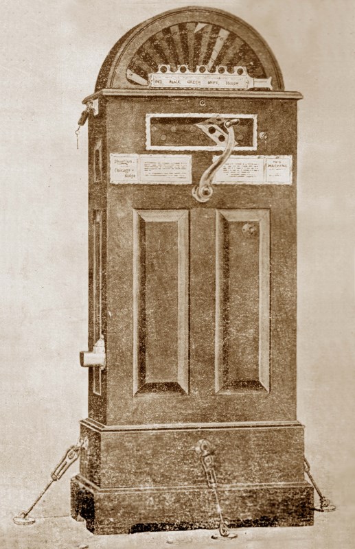
Advertising Plate for One of the Many Chicago Ridge Variations, Depicted with Floor Tie-Downs to Prevent Rocking
In reality a good portion of the machine is still purely mechanical – all of the wheel spinning mechanism and the coin head are mechanical. The handle mechanism release and the coin payout are triggered by battery powered electromagnetic actuators, which greatly simplifies the complexity of the overall mechanism.
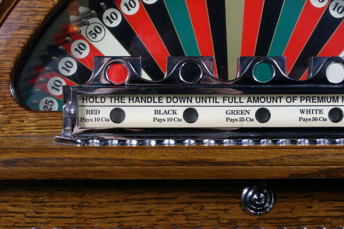
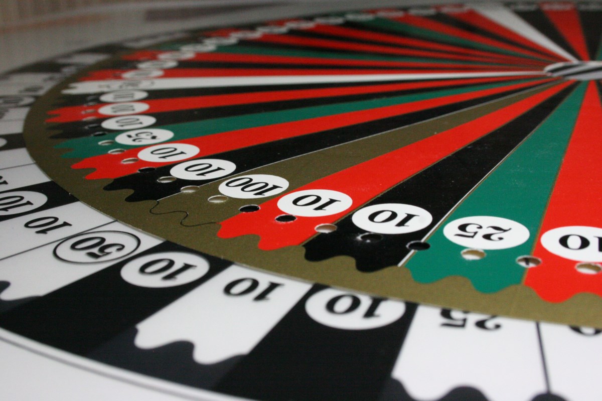
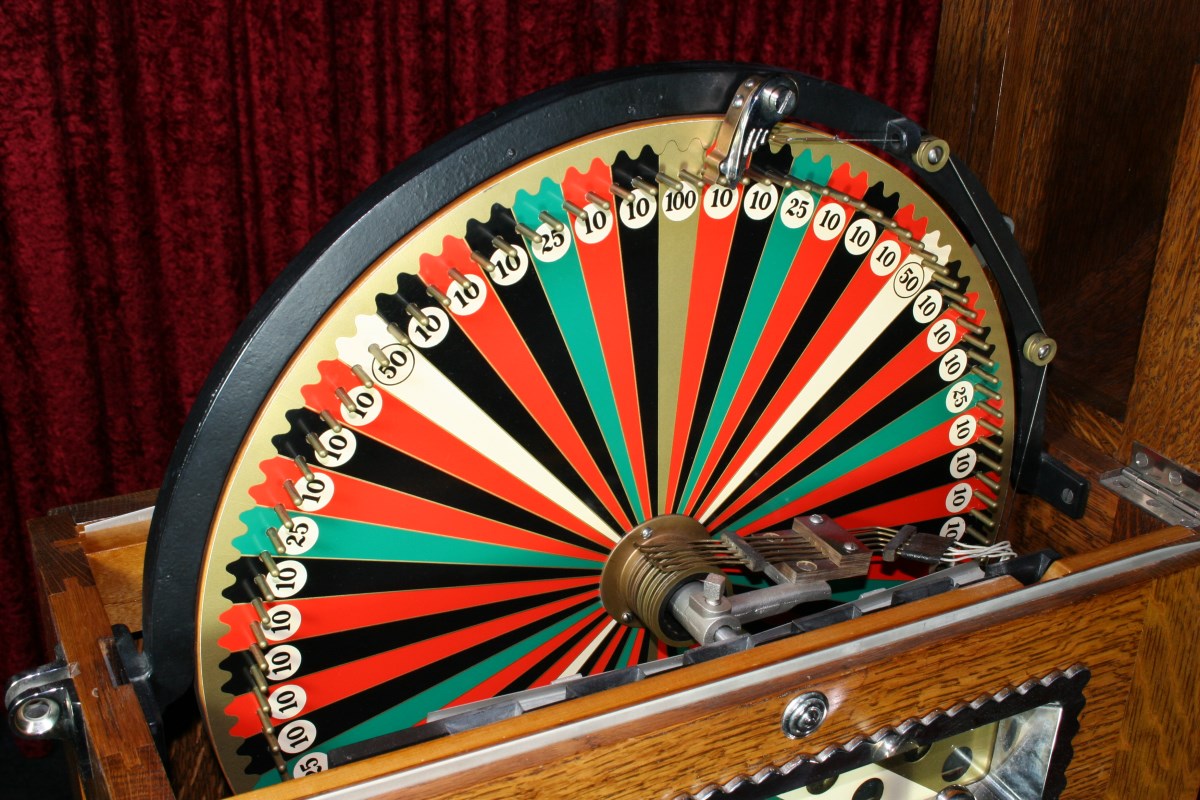
The Numbers on the Color Sectors Indicate the Payout if Player Lands on the Color That Was Bet
The wheel has colors assigned to the amount of the payout, with higher payouts attached to less frequent color sectors. The player wins the amount indicated on the wheel if the color(s) played and the color(s) landed on match. Betting on all five colors will result in a guaranteed payout, but no guarantee of coming out ahead. The player only wins the amount on the winning color sector.
The odds are never in the player’s favor, and the probability of winning is even less than you would surmise by calculating the numbers of sectors and respective payouts against all possible outcomes. This can be attributed to a couple of hidden “features” that will be mentioned later.
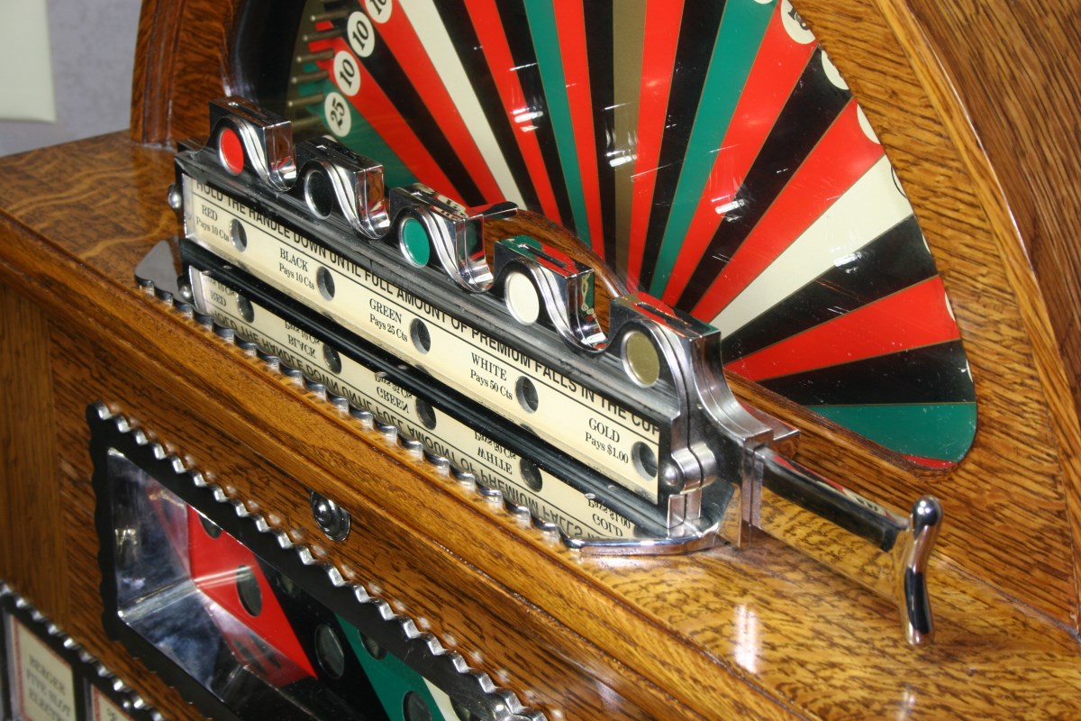
This Coin Slide Lever Prevents Cheating By Blocking Direct Access to Coin Mechanism
The play sequence is begun by inserting a coin or coins on the desired colors slots in the coin head. The coin slide lever on the right side of the coin head is pushed left, and the coin drops into the coin receptor below, whose slots are offset laterally from the coin-insertion slots above. This coin closes an electrical circuit that triggers a release actuator for the front handle.
The handle is depressed and the mechanism releases at the end of the stroke, spinning the wheel and winding an internal gear clock that ticks off and allows time for the wheel to spin, stop, and payout before disabling the electrical circuit. The wheel accelerates up to speed, and then coasts to a stop. A spring-loaded finger pressing on the wheel’s brass pins enters one of the colored segments, closing a circuit to trigger a payout. Electromagnetic actuators similar to those used for telegraph sounders activate the release of groups of coins lined up in an inclined guide inside the cabinet. The timer clock runs out and disconnects the battery, reducing the opportunity for cheating and eliminating the chance that an errant coin will drain the batteries.
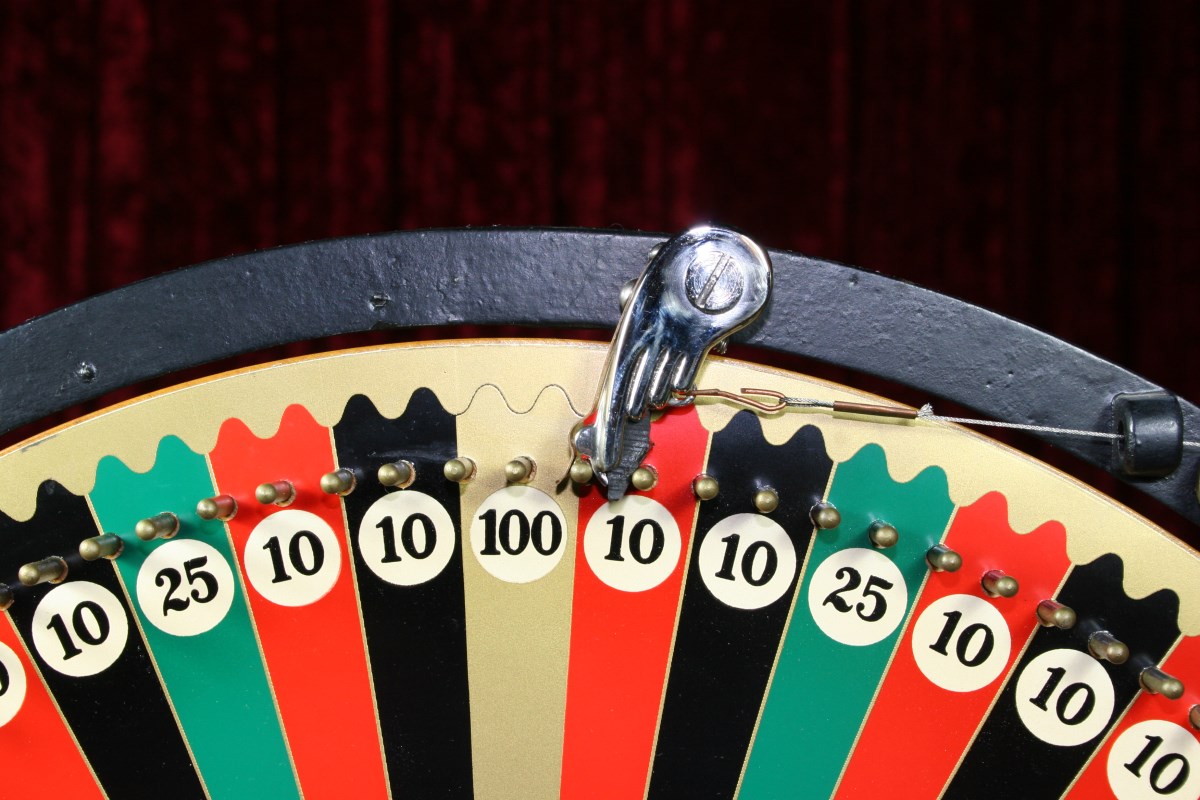
This Finger Stops the Wheel and Closes an Electrical Circuit to Activate Payout
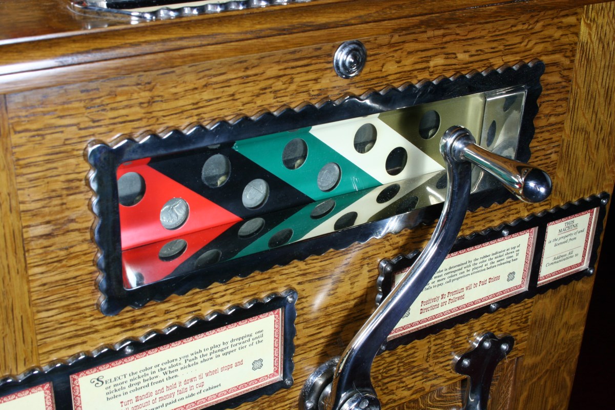
This Window Shows the Last Coins Played to Permit Slug Detection
Literally a Basket Case
I find it a little surprising that in this condition someone actually cared enough to keep all of the parts together:
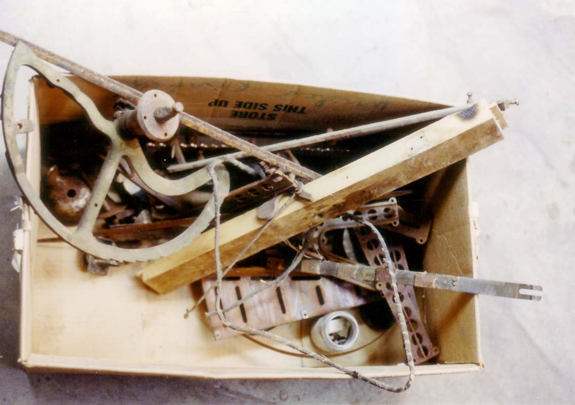
Actually a Box, Not a Basket
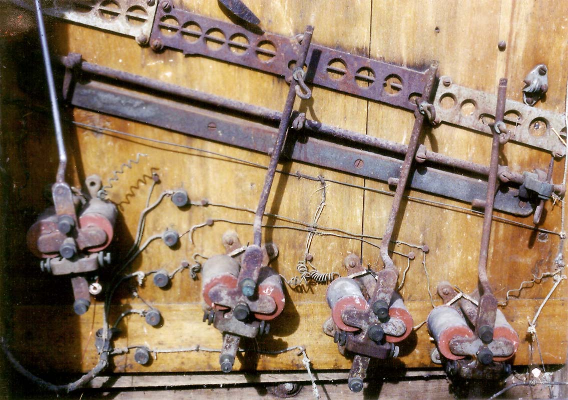
Electromagnetic Payout Actuators – Rusty, But All There
This Would be “Excellent Condition with Nice Patina” on eBay
American Picker’s Rusty Gold!
The photos above show what the Berger looked like when I bought it. I didn’t know anything about these machines at the time, and information was a little harder to dig up before the Google era. I did have two photographs given to me by my good friend Kevin Hammerbeck (who sold me this pile of junk!) that were taken from a Berger restoration he had completed a few years earlier. I actually studied these under a microscope located in the lab where I worked, taking pictures of the enlargements so they could be reviewed at home in my shop.
Many key items were missing or broken, but there were also enough parts intact that it still qualified as a restoration project rather than just a replication. Broken parts would not be a problem to remake, but the entire coin head assembly and the top of the wood cabinet were missing, and I needed something to go by to be able to reconstruct these items accurately.
With a little guidance (and his Coin Slot Guide #23) from the late great writer, historian, and collector Dick Bueschel, and a few well-placed inquires I was able to get in contact with restorer Gary Taplin, who ultimately provided me with all of the information I needed. Gary had in his possession a similar machine and took the time to disassemble the coin head, send the parts out to a foundry for recasting, and shoot two rolls of film of all the details I was missing. I did not end up using the recast parts, but they were invaluable as a guide for making new patterns that were used to cast the final parts.
Gary’s information was key to this restoration, and although I thanked him profusely at the time, looking back at the detailed closeup photos (some staged with rulers to provide accurate dimensioning), I’m not sure I could have thanked him enough.
The Restoration
Metalwork
Armed with the information I needed, work began on the mechanical parts. Since I would be casting the reproduction parts in red brass using my home foundry, it was safer to try to schedule this portion of the project for dry weather in the summer. Moisture and molten metal do not mix, and even an errant snow flake can result in a mini-explosion.
All except one of the internal cast iron levers for the wheel-spinning mechanism were broken but could be used for pattern-making guides. New wood patterns were made for all of the parts to exactly match the function and appearance, except they were scaled up slightly in size to allow for casting shrinkage of red brass. The same procedure was followed for the missing coin head parts; red alder was machined and assembled to match the recast parts that Gary Taplin had sent. The patterns were filleted with wax and sealed with a non-stick graphite coating.
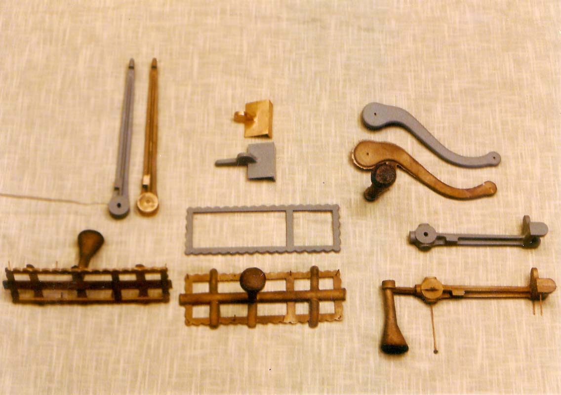
Old Photo of Rough Cast Parts Next to Wood Patterns
When all of the wood patterns were finished, Petrobond sand molds were made over the next couple of weeks and the castings were poured in several sessions. Home casting is for me an iterative process, and 100% yield is not something I will ever reach. In particular the thin scalloped frames that border the instruction cards on the front of the cabinet were a royal pain. The molten metal would never make it all the way through the mold before freezing, and I finally had to cut runners in the mold to feed every part of the frame, and mill the runner metal off later. I still have a pile of these failed castings in my brass stock, but in the end every part was reproduced faithfully in high quality, gas-free brass.
The rough metal castings were trimmed, machined, fitted for function, and decorative parts were polished. All of the brass parts were flashed with acid copper for a uniform base and then heavily bright nickel plated in a modified Watt’s solution. Plating at home is never fun, but it is the lesser evil versus trying to deal with plating shops for small (don’t bother us) or valuable (because we’ll lose it) parts, particularly on a schedule (we’ll get to your job when we’re out of real work). I can do non-cyanide flash copper for pot-metal and steel, acid copper for heavy build & buff, and both satin and bright nickel. It is never fun, not even close, and like casting it is never a 100% yield endeavor. But eventually you get there.
Metal parts that were salvageable were sandblasted, repaired or brazed as need, and plated or painted.
The timer clock and the wheel spinning mechanism both needed replacement coiled flat springs that were fortunately available in the correct sizes from Empire Clock in St. Paul, MN.
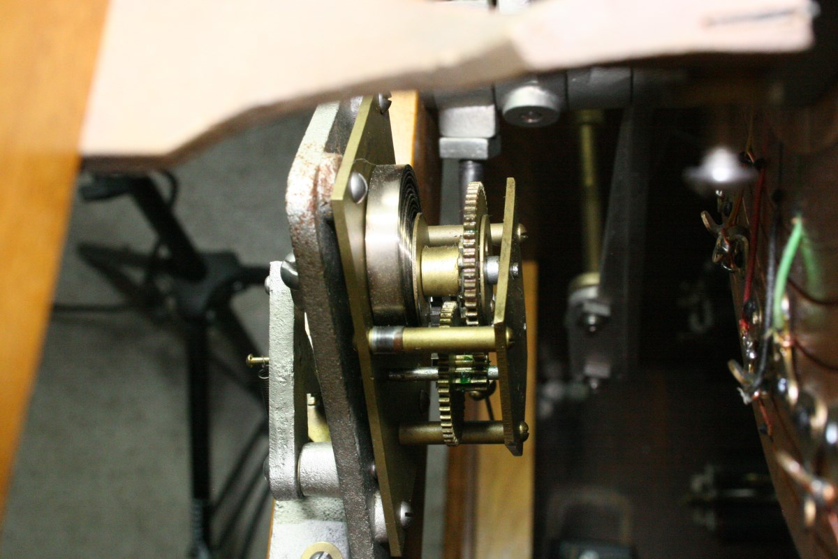
New Spring in Timer Clock
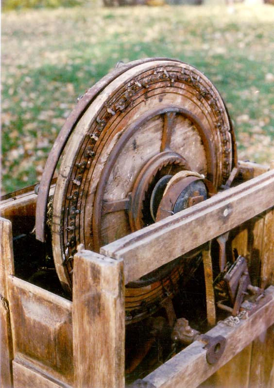
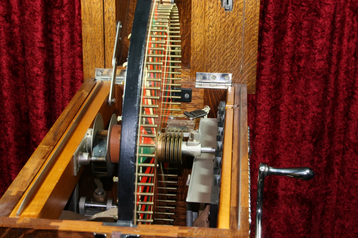
Large Wheel-Spinning Spring is Contained in Reel on Left of Shaft
Woodwork
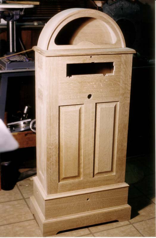
Completed Cabinet Unfinished
As a restorer I always try to use original parts whenever possible, even if it requires more work to make them presentable than it would to reproduce. In this case there wasn’t any need to fret over what to save, because the cabinet was partially missing, and what remained was trash.
Rebuilding the cabinet was the most straightforward part of the entire project, and the goal was to create an accurate copy of the original with identical joinery.
A little more than 600 board feet of 5/4 tiger-striped quartersawn white oak was purchased in the rough, which usually makes the grain striping difficult to judge. But I always sneak a small plane into the lumberyard to skim the fuzz off the rough wood so I can see what I’m buying. From this larger lot I was able to choose a subset of the best grain patterns for panels and the trim pieces.
The only real challenge with the cabinet woodwork involved replicating the unique cutter shapes for the raised panels and the moldings. Nothing was commercially available that would match the original shapes, so router bits had to be hand-ground to match sample cross sections of wood trim that were cut from the original cabinet.
The profile depth of the raised panels was too difficult to reproduce with a custom router bit, so I ground three matching molding head cutters to match the panel profile. All panel edges were then milled using the molding head cutter in the table saw, guiding the panels vertically on edge instead of flat. No compromises were made here; the routed edges are all exact matches for the originals.
Even the curved top was not very difficult to make. It looks like a solid, steam bent piece of 3/4″ oak, but it began as a solid flat 3/4″ thick piece that was kerfed on one side at about 1/2″ intervals with a thin blade. The kerf depth was about 5/8″, leaving 1/8″ of bendable thickness.
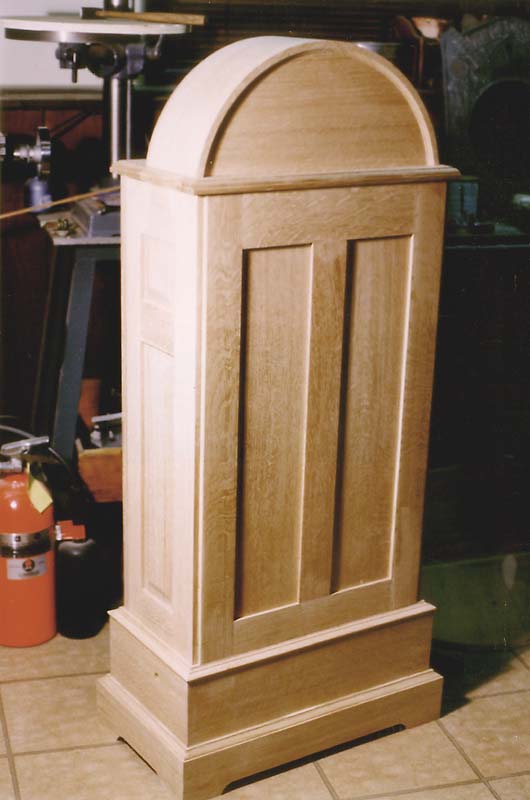
Rear View
Another panel of 1/16″ thick QS oak of the same size was prepared as a veneer to cover the kerfs that would otherwise be visible on the inside of the bend. Both the kerfed and the thin pieces of oak were then soaked in water overnight.
The next day both pieces were heated and then clamped over a form of the exact radius for the final part, with the veneer on the inside and the kerfed piece on the outside of the laminate (kerfs facing in, of course). This remained clamped until both pieces were thoroughly dry.
When removed from the form, both pieces of wood had a little spring back, but the final lamination would fix that. A paste was made using epoxy and either cabosil or microballoons, and spread to fill all the kerfs. The pre-curved veneer was aligned to the inside and the assembly clamped to the form until the epoxy cured. Upon removal from the form, the lamination had no spring back, and the only clue that it was not a solid piece of wood was at the edges where the kerf cuts were visible. This would be covered by the trim in the final assembly.
To finish the top, the slight bumps at the kerf lines were first belt-sanded to minimized the ripples. But the final important step to ensure that no ripples would be visible in the glossy finish require a sanding form to be made. This was nothing more than a fairly long sanding block cut to a slightly larger radius than the radius of the top. A strip of sandpaper adhered to the concave curve of this block would sand only the peaks. This was a little hand work, but was a very important step because even a soft orbital sander pad would not definitively remove the kerf ripples that telegraphed through to the bent surface of the top.
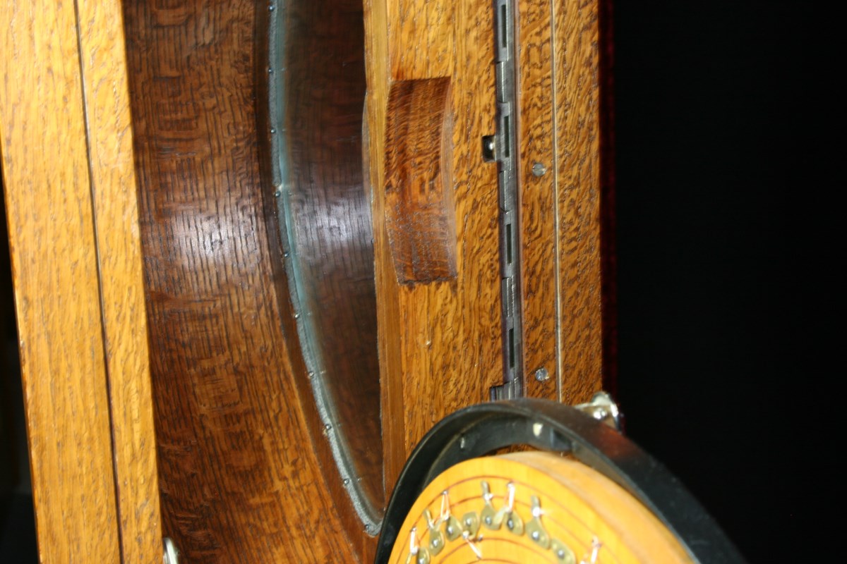
Inside of Curved Top is Veneered to Hide Kerf Cuts
The Curved Top Is Rigid and Smooth with No Hint of Internal Kerfing
There were two more woodwork projects that were not part of the main cabinet. The original color wheel was made of three laminated layers of wood and was warped. It also was quite complex in that it had to have precisely located holes for the brass pins, and it also needed grooves on the back through which wiring could connect groups of pins to each other and to the commutator hub on the front of the wheel.
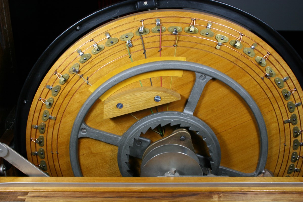
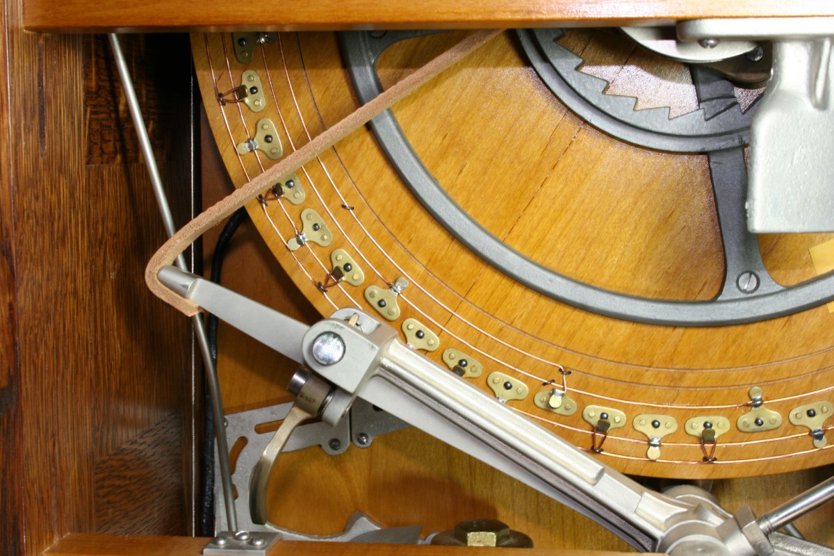
Wheel Wiring – Sectors of the Same Color are Tied Together
I had hoped that the wheel might be salvageable if I straightened it using the same kerf /clamp/laminate process that was used on the top. All the metal parts and wiring were removed, about 1/8″ was planed off the front face, and a grid of kerf cuts was made across the face. This made the whole disk quite flexible.
Next the kerfs were filled with the same epoxy-filler paste, and a new piece of alder laminated to the front. It was clamped perfectly flat while curing. Although it came out much better than it was originally, I gave up at this point and just laminated a whole new wheel using three cross-oriented plates of red alder. The pin holes were indexed and drilled on a milling machine. Grooves were routed for wiring, the pins were installed, and the wheel wired.
The last piece of woodwork was the mechanism board, which was a separate assembly of 1/2″ alder that provides a mounting surface for the mechanism components, which then in turn is mounted to the inside of the oak cabinet. The original construction of this board defied good woodworking practice, with the grain of the top and bottom end strips running horizontally, but I replicated it the same way.
Electro Mechanical Work
Aside from the color wheel, which is part of the electrical circuit that activates payout, several other items needed attention.
Underneath the coin head and attached to the mechanism board is an insulator panel made of some type of early plastic material that predates Bakelite – possibly a celluloid. It has straight and tapered channels that funnel and guide the nickels from above into brass contacts, allowing the nickel to close a circuit to trigger the electromagnetic actuators for handle release or coin payout.
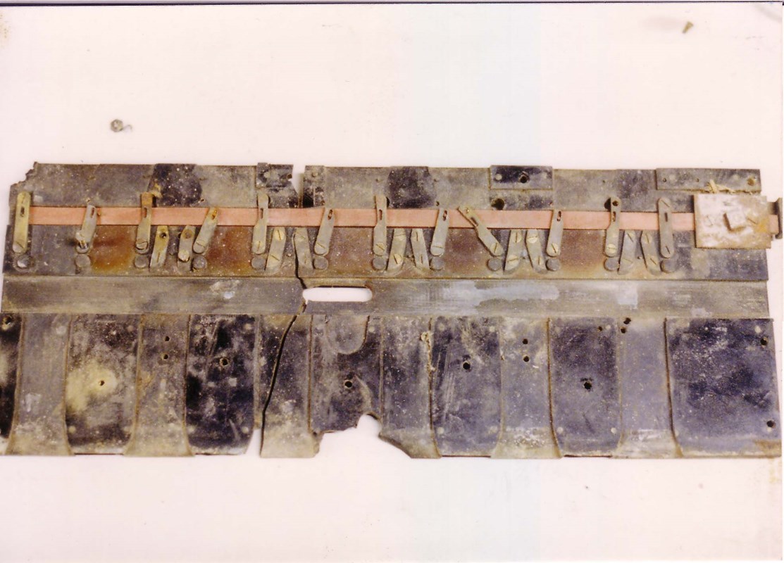
Not an Egyptian Artifact – This was the Plastic Coin Contact Panel as Found
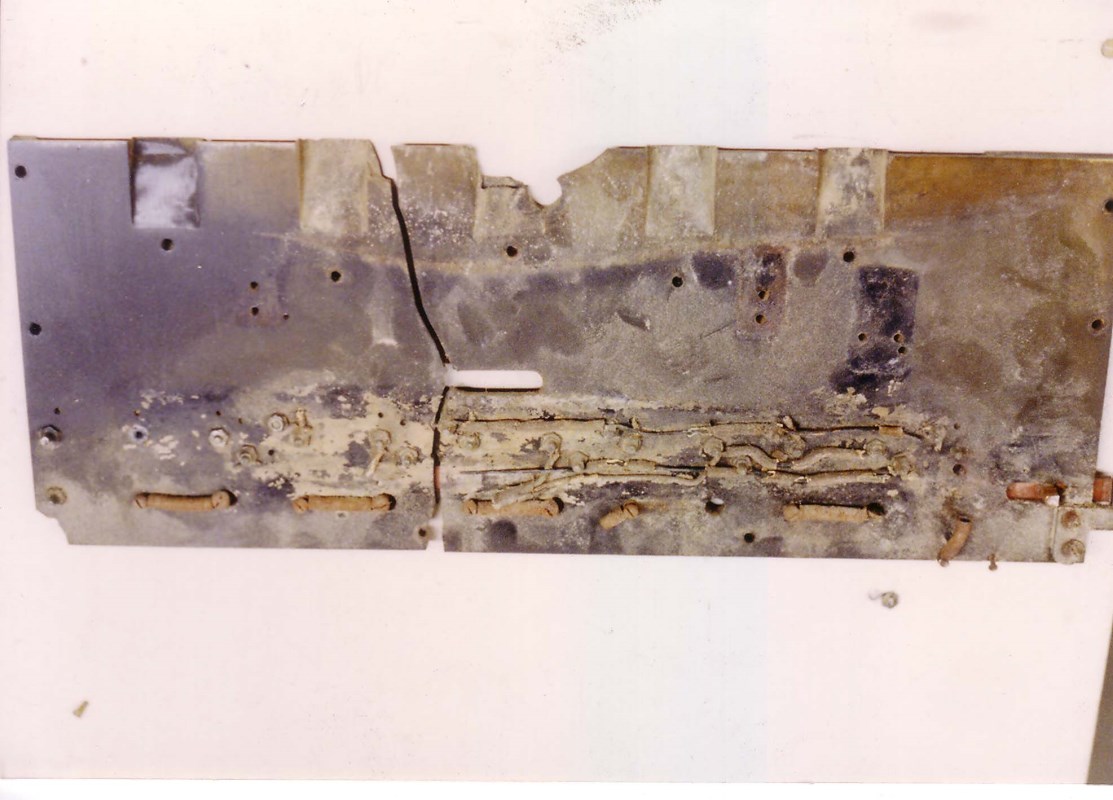
Rear View of Contact Panel
The original was quite a mess, with fractures and some pieces broken and missing. This piece of plastic was quite complex and if reproduced would have required a great deal of precise machining. But despite the terrible condition it looked repairable, and on top of that it looked like it would be repairable to a new appearance as well.
Mechanism Board Reassembly – Note Repaired Contact Panel
All of the contacts and other components were removed from the panel and the fragments were fitted together. This was a perfect application for some leftover structural gray epoxy material that had been used on the ailerons of the airplane that I was building. It may have been a 3M product, and it was similar to a light-colored JB Weld – very strong, sandable, and even machinable.
This epoxy was used to first bond the broken parts together, and then applied as a filler for any blemishes at the repaired cracks and elsewhere. To build up damaged corners and missing chunks, walls or dams were devised to retain the epoxy as the new sections were cast onto the original part.
After curing the epoxy sections were machined or sanded to blend into the base material. At this point the panel was structurally sound and cosmetically perfect except for color. The panel was finish sanded and sprayed with a thin satin black epoxy. After the repairs and paint, the panel looked like a newly molded part with no indication that there were ever any cracks or chips.
With the contact panel restored, the five dual-coil electromagnetic actuators were to be given what was expected to be a simple mechanical cleanup and replating job. As it turned out, there were some internal broken wires on the coils, so all of the coils were removed from the mounts and restored individually. The red fiber bobbin washers for the electromagnets were in good shape, but the cotton-insulated wires and the cloth wraps for the electromagnets were not.
The electromagnet coils were stripped of their cloth covers, and new cotton-insulated wire pigtails were spliced into the magnet-wire ends of the coils. New strips of a heavy black coarse-weave linen were used to cover the windings and the pigtail splices. They were sealed in place with a few coats of orange shellac, which resulted in a very original appearance.
This procedure was repeated for all ten of the electromagnet coils, and all of the of the newly-plated actuator parts and coils were assembled and adjusted for movement.
This Electromagnetic Actuator Releases the Front Handle
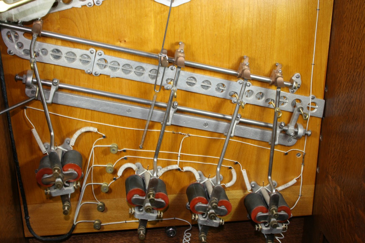
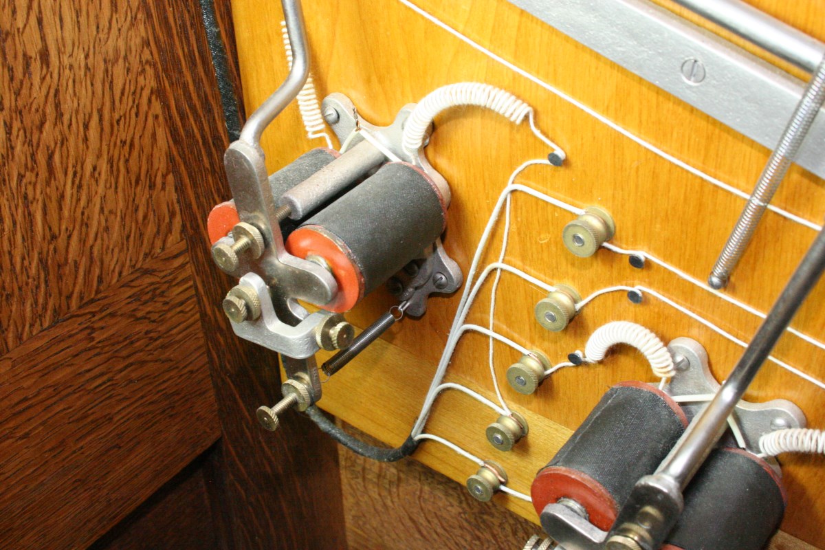
These Actuators Release Coins Filling the Guides Above
Actuators Look Like Telegraph Sounders
New Wire Pigtails and Fabric Covers on Coils
Brass Pins at Wheel Edge are Wired to Rings on the Commutator Hub
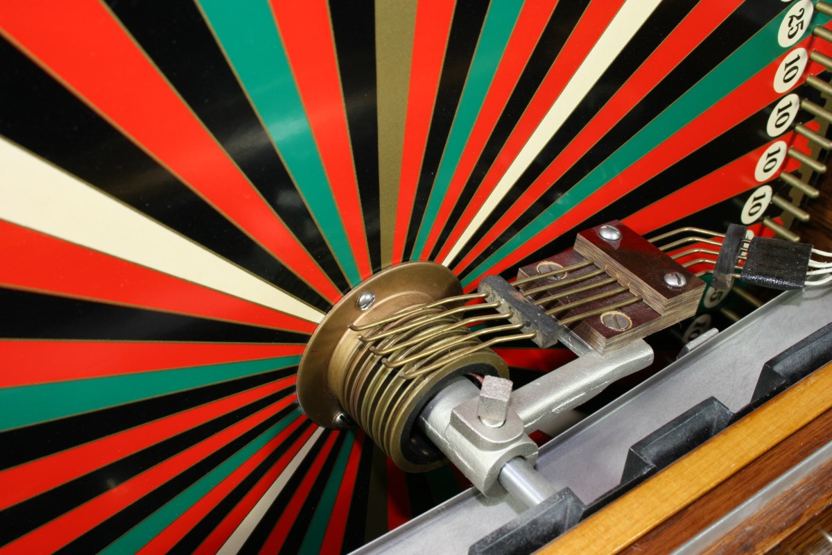
Detail of Commutator Hub
Color Wheel Artwork
From the beginning of the restoration project, there was a dark cloud looming on the horizon knowing that there would be a need at some point to print a new paper color wheel and card for the coin window. At the time of the restoration it wasn’t quite as easy to simply order a large color print with archival ink as it is today. And even now there would be some reluctance to use an electronic printing method that might fade or deteriorate in the next hundred years or so.
Around the time of this restoration we had been experimenting a little with home screen printing for other reasons, primarily for use in slot machine restorations where nothing else was available. Like metal casting and electroplating, screen printing on an as-needed basis for personal projects is a low-yield proposition, even for a single color. The Berger color wheel would require four very accurately registered colors (red, black, green, and metallic gold) plus the white background color, and this was not trivial for a manual operation.
Screen Printed Paper Wheel & Artwork Transparencies – This Was a Reject
My wife spent weeks generating the four separate layers of artwork (with a custom font) to match the original wheel artwork. The colors would be printed one at a time, with days of separation between sessions. Many sheets would be printed in a single color, allowed to dry, then printed again with the second color, and so on. Each color required creation of a new screen, and for a basement operation consistency is always a problem.
A large stack of off-white card stock blanks were cut before attempting the first prints. Many prints would be lost along the way in the process of aligning the registration each time a new color was printed, and even more would be rejected due to random flaws that can occur every time you make a squeegee pass.
Only one print needed to survive the gauntlet of potential mistakes, but in the end we had a good quantity of successful prints to choose from. A good print was selected, the wheel and card were cut, and the pin holes in the wheel were punched on a homemade tool that had been made on the milling machine for accuracy.
Wood Finish
This is usually my least favorite part of woodworking, and many projects have been botched at this point. Historically speaking, paint stripper has been my most commonly used finishing material.
Somewhere on my wood rack I keep a sample piece of a quartersawn oak cut from the back door from an old slot machine – this has the look that I try to achieve for most antique restorations. The finish is moderately dark overall, with a hue veering into a reddish-brown. The porous grain of the oak is very dark, darker than burnt umber, and the finish itself clearly has an amber tone if you scrape off a sample. The flecking from the medullary rays is considerably lighter and more amber and less red than the surrounding color, and visibility of the rays is due primarily to the color difference, and not so much the reflectivity of the rays. Because of this the rays show distinctly under all viewing and lighting angles.
I have experimented with oak fuming and have tried many different fillers, stains and dyes, but the favorite process I use to this day is not something you would be likely to find in Fine Woodworking magazine. The biggest problem I have is in trying to darken new wood sufficiently, and I think dyes would help here, but I just don’t experiment much anymore. I really don’t understand stains and dyes. Some will bring wood to life, highlighting grain and causing flecking to reflect and glow. Yet sometimes for no immediately apparent reason others will uniformly color the grain like a thinned brown paint and give the wood all of the character of a Formica counter top.
Wood Flecking Shows Good Contrast, But Could Be Better
The combination I arrived at for use on the Berger is transparent enough to let the rays jump out and reflect light and also make the finish appear to have some depth. Unlike my gold-standard antique sample, contrast of the rays does depend more on lighting and viewing angle. There is a good color difference between the rays and the surrounding wood, but it is not as distinct as on my antique sample.
I started finishing the Berger cabinet by using a very deep-tone paste filler to darken and partially fill the open grain lines of the oak. When this was dry and sanded, I stained everything with a 50/50 mix of Red Mahogany and Jacobean Minwax Wood Finish (this is the solvent-based finish). After wiping and drying, it was stained again to get a little darker tone. This left the oak with an excessively reddish hue, but this would be corrected with the finish coats.
To emulate an old yellowed finish I used several coats of a weak mix of orange shellac chips dissolved in alcohol. Generally tinted finishes are a pain to apply; uniform thickness is important as it affects the final color. In this case the amber shellac was being used to offset the overly red wood stain, and the final finish was very close to how I wanted it to end up. Applying many thin coats is one way of achieving a more uniform average film thickness, but shellac requires careful application to avoid melting and dragging previous coats.
The finish on the Berger has received many compliments, but admittedly it is not an authentic finish. I suspect there is a better way to replicate the antique look of my sample, perhaps with aniline dye coloration of the raw wood followed by tinted varnish rather than shellac. The real key that has eluded me is finding a dark red stain or dye that provide a high contrast for the flecking, and at the time I could not improve on the combination that was used. I do still use this Minwax-shellac finish on most projects today though with a higher percentage of red mahogany and less Jacobean in the stain mix.
As a final step the entire cabinet was hand rubbed to a soft sheen using a felt block with rottenstone and oil, followed by several applications of a carnauba wax mix.
Assembly
This is generally the fun part of any restoration, and that was the case here. At this point everything has usually been fitted and tested multiple times prior to painting and finishing, so it is usually just a matter of screwing everything together and making a few final tweaks.
The mechanism board was assembled outside of the oak cabinet. All components were mounted on the board, and everything was wired with new cotton-insulated wire, identical in appearance to the original, that I had luckily found at a surplus store. The board was installed in the cabinet, the wheel assembly was mounted, and with a few spring tension adjustments this restoration project was done.
Final Notes: Two Cheating Mechanisms
There are two more interesting parts of this machine that are worth mentioning, both of which tilt the odds in favor of the house.
1) The Randomizer
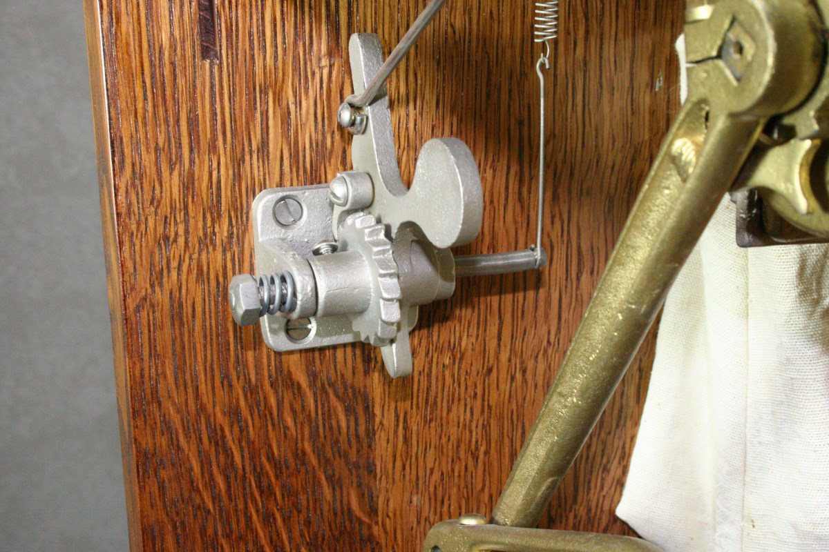
Randomizer – The Ratchet Shaft is Slightly Eccentric, Changing Spring Tension as Ratchet Wheel Advances
The first mechanism is an anti-cheating feature that helps prevent the player from learning to predict where the wheel will stop relative to its starting point.
If wheel spins were very repeatable it is conceivable that a player could learn approximately how far the wheel advances with each spin. This is sometimes referred to as rhythm play. For example, if through repeated plays it is observed that the sector on which the wheel stopped was on average 10 sectors clockwise from the starting sector, this knowledge could be used to anticipate which color would be best to bet on for the next play.
The Chicago Ridge’s spinning mechanism is fairly crude and it would be surprising if the repeatability was very good, but nevertheless a randomizer mechanism was added that would further reduce the predictability of play.
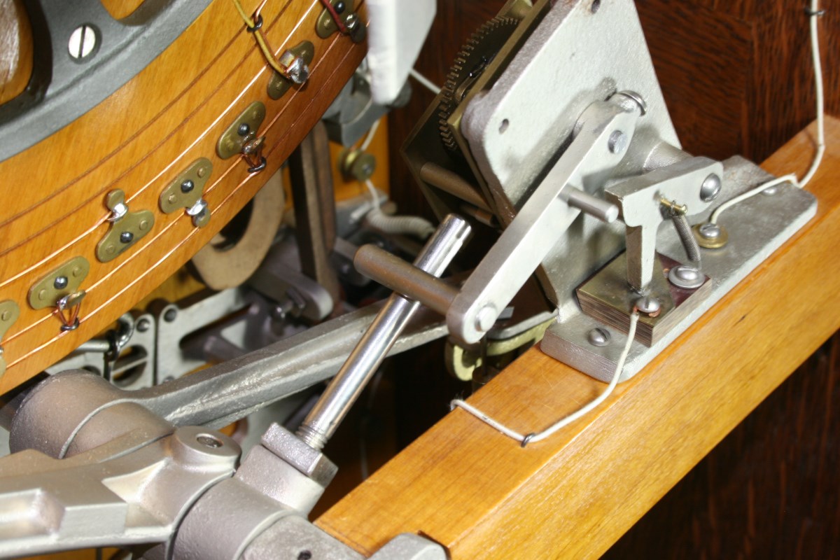
A ratchet wheel with a slightly eccentric shaft is mounted on the left side of the cabinet (viewed from the rear). A spring-loaded pawl engaged in the ratchet wheel is connected to the main handle shaft through a link rod, allowing the ratchet wheel to advance one tooth each time the machine is played.
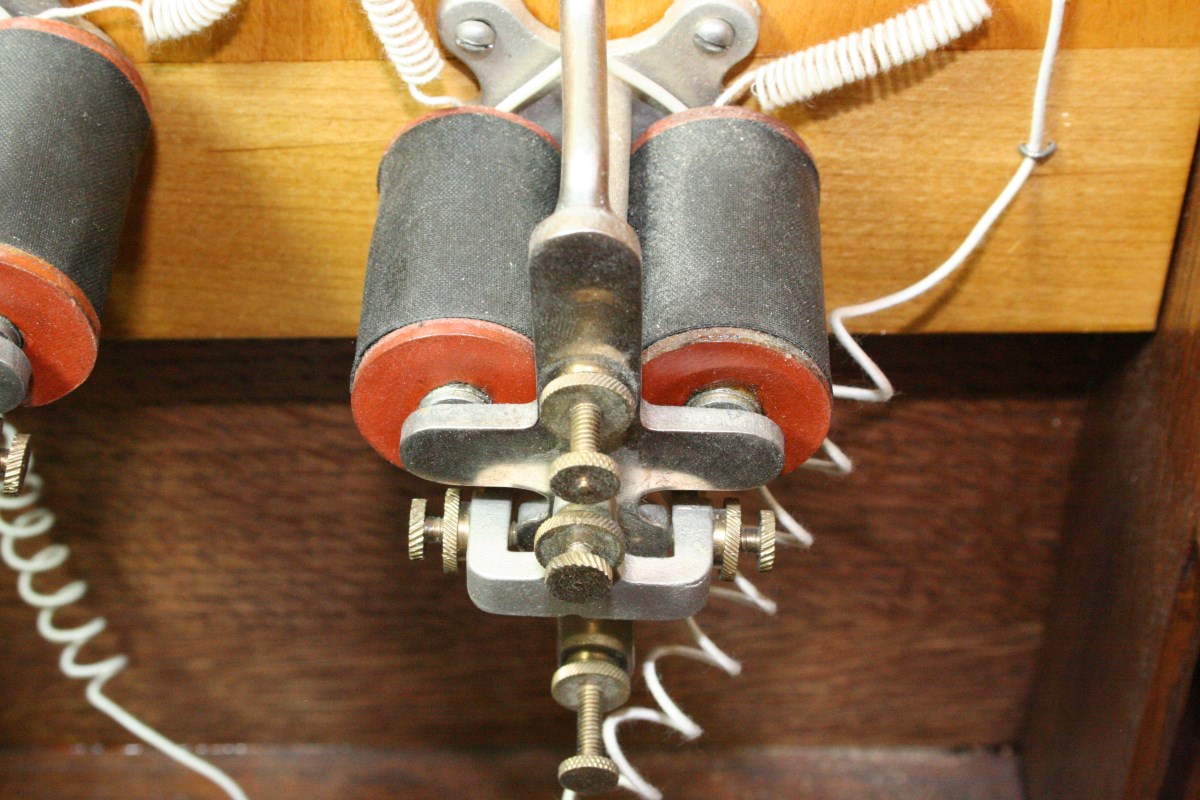
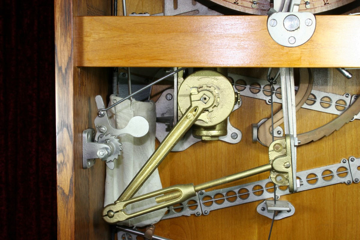
Cable and Pulleys Allow Variable Spring Tension to Alter Wheel Stopping Position
The top finger that stops the spinning wheel is spring tensioned through a steel cable and a pair of guide pulleys. But instead of the spring attaching to a fixed point in the cabinet for a constant tension, it is attached to the eccentric shaft of the ratchet wheel. Each time the ratchet wheel steps through one complete revolution the spring tension goes through a complete cycle of minimum-to-maximum-to-minimum. This slight change in the spring tension on the finger affects how far the wheel advances with each spin, but in a very subtle way. Neither the wheel spins nor the perturbation introduced by this randomizer are totally random, but together they could effectively disrupt rhythm play.
2) The Bug
The second feature is intended to reduce the odds of a player winning the highest payout of $1.00, but in a manner that is not apparent to the player.
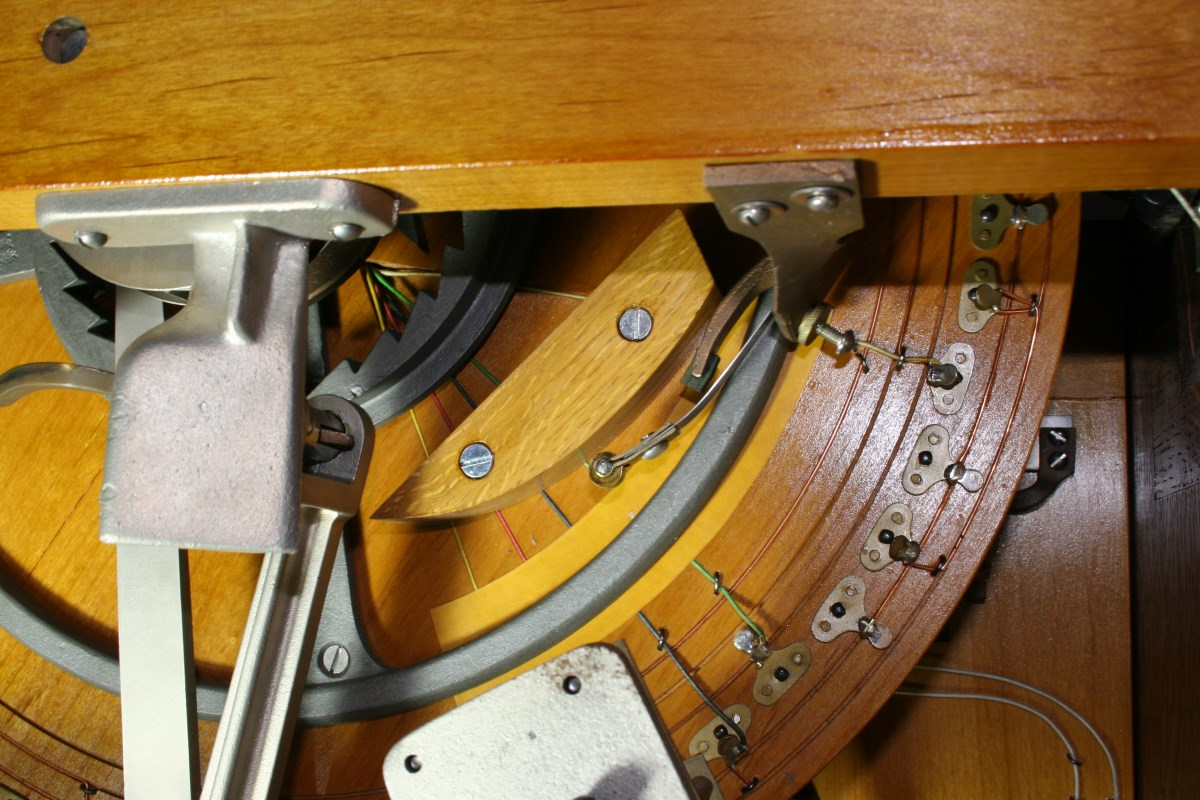
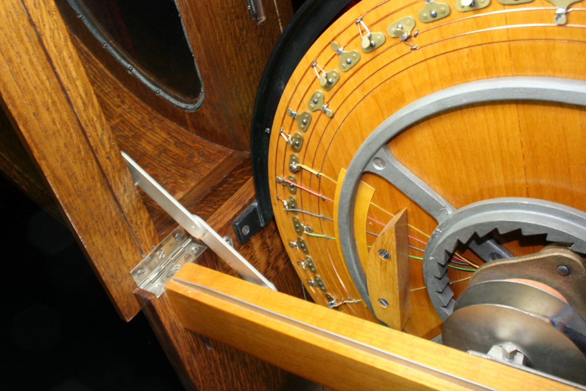
Wood Block and Spring Roller Prevent Wheel From Stopping on One of Two Top Payouts
A block of wood is strategically located on the back of the color wheel, and a spring-loaded roller wheel mounted to the cabinet just touches a corner of that block at one specific position of the wheel. That position is chosen so that the corner of the block contacts the roller when the wheel is poised to stop on one of the two gold $1.00 sectors. The spring tension of the roller wheel is adjustable so that the wheel just kisses the corner of the block.
If the wheel is naturally inclined to stop at this one gold sector, the roller will either make it stop a little short of the sector, or just push it past the sector. The roller is set so that the wheel doesn’t bounce backward as it approaches the gold (this would be obvious), but it just suggests that the wheel stop before or after.
The odds of winning on gold as calculated by the player would be (2 gold sectors)/(56 possible stops) = 1 in 28, but with one of those sectors disabled the chances are 1 in 56.
This type of cheat is generally referred to as a bug, and was used in 3-reel slot machines as well in later years. The idea is to give the appearance that a position is available to stop on, but it is mechanically skipped without any hint of unnatural behavior.
Video Demonstration of the Mechanism
More Pictures
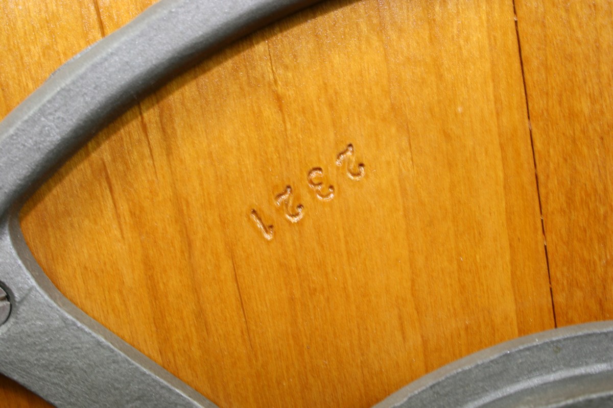
Serial Number Stamped on Back of Wheel
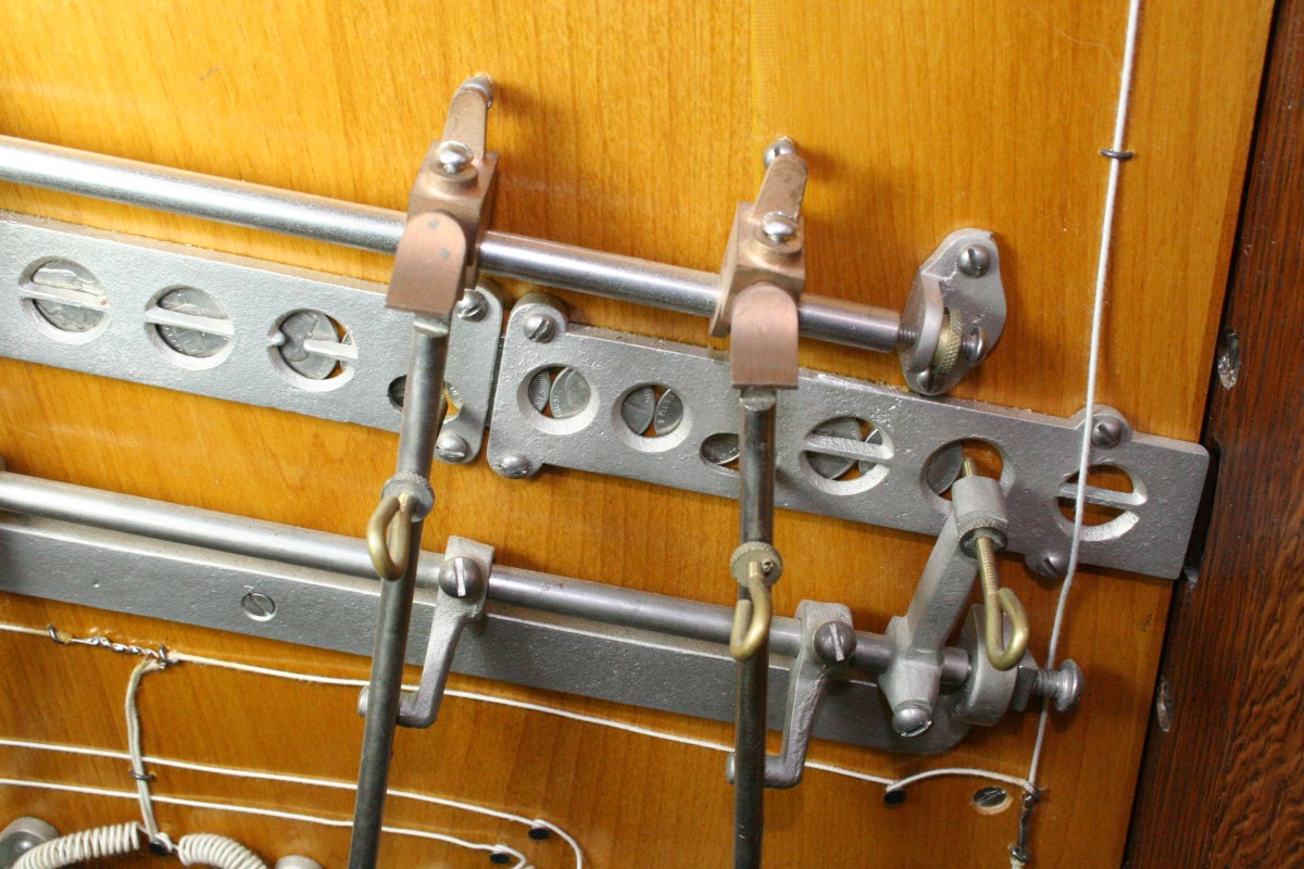
Only Second Lever From Left is Free to Rotate on Shaft
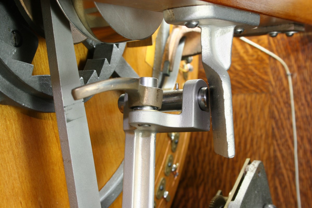
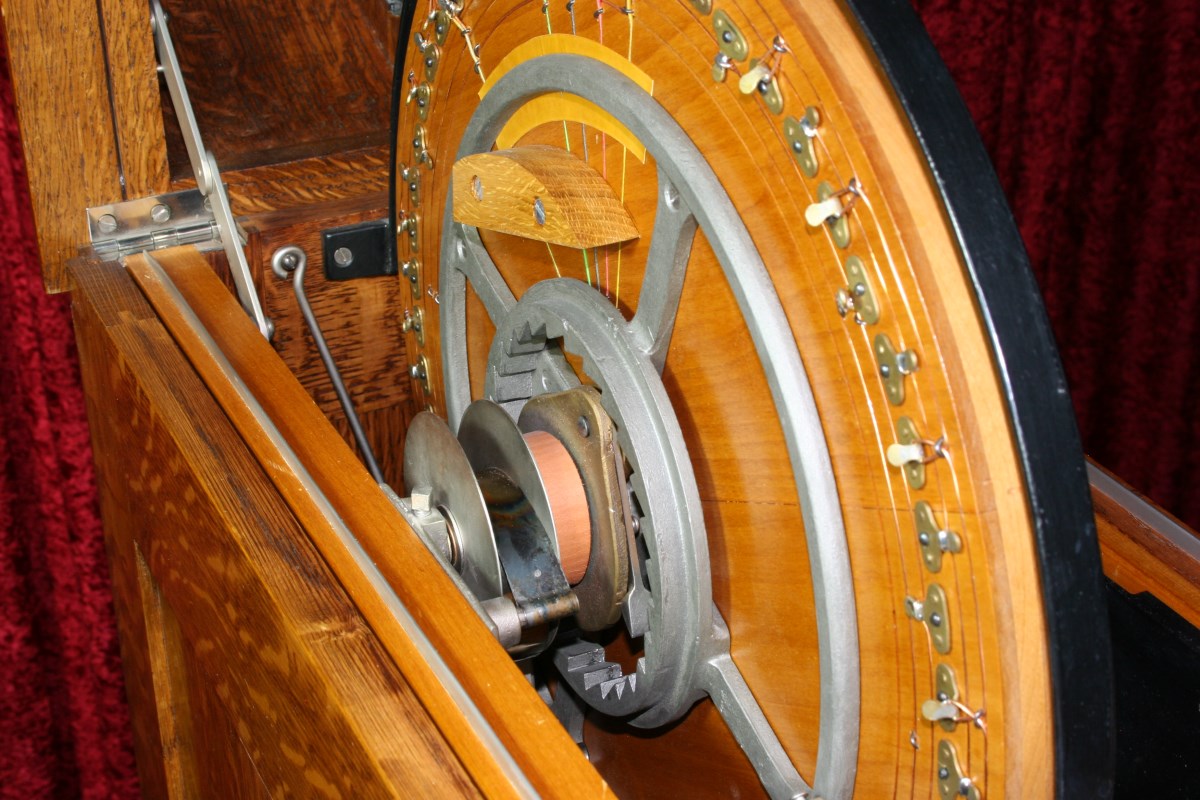
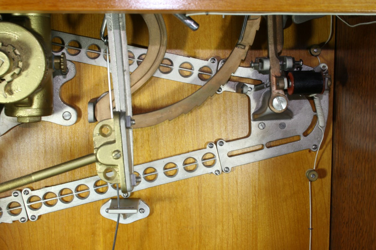
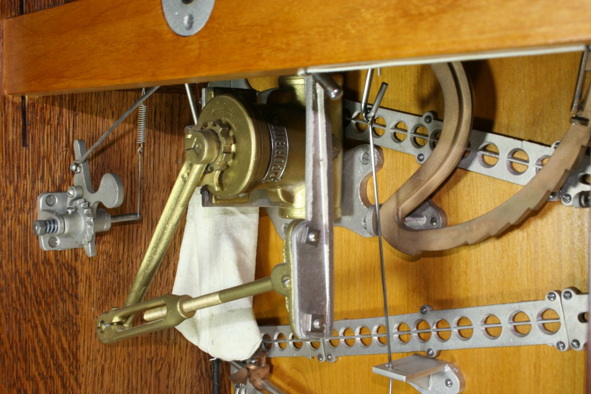
Part of Wheel – Spinning Mechanism
The Cloth Bag Collects Overflow Coins When Ramps are Full
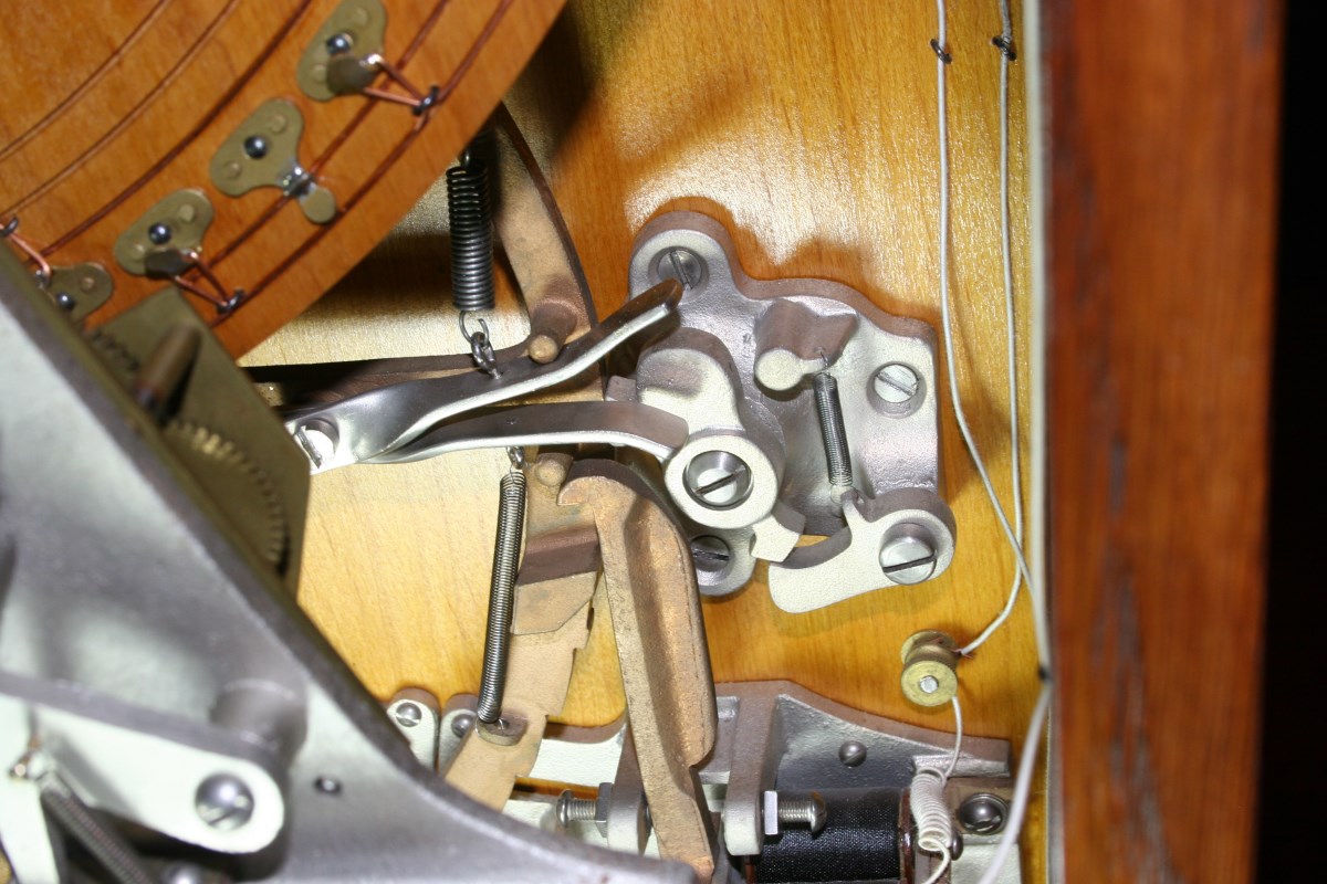
Electromagnetic Latch for Releasing Handle
A Fluid-Damped Door Closer Slows Return When Handle is Released
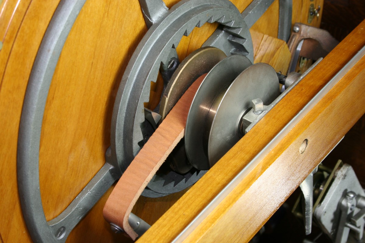
Leather Strap Winds the Wheel Ratchet When Handle is Depressed
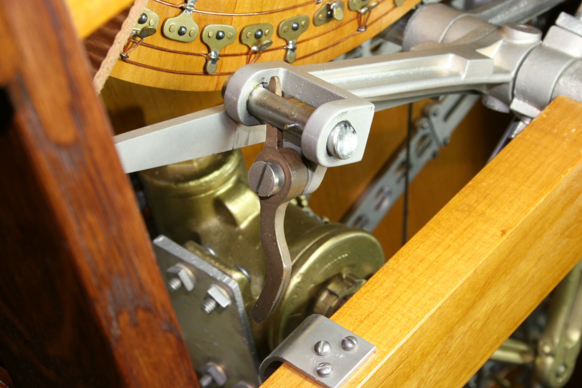
Latch Pin Ready to Release and Allow Wheel to Spin
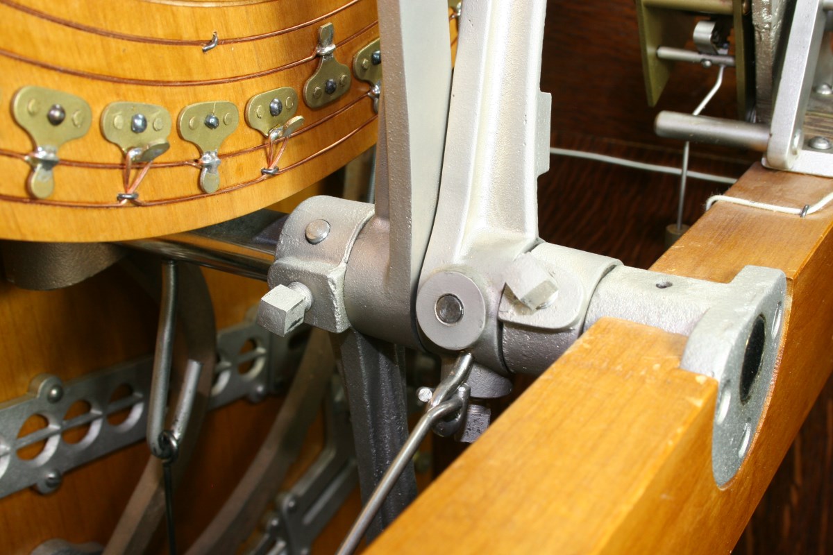
Shorter Lever With Pin is Pulling the Longer lever as Handle is Pressed
Timer Clock is Winding Up as Front Handle is Pressed
Hinged Top Detail
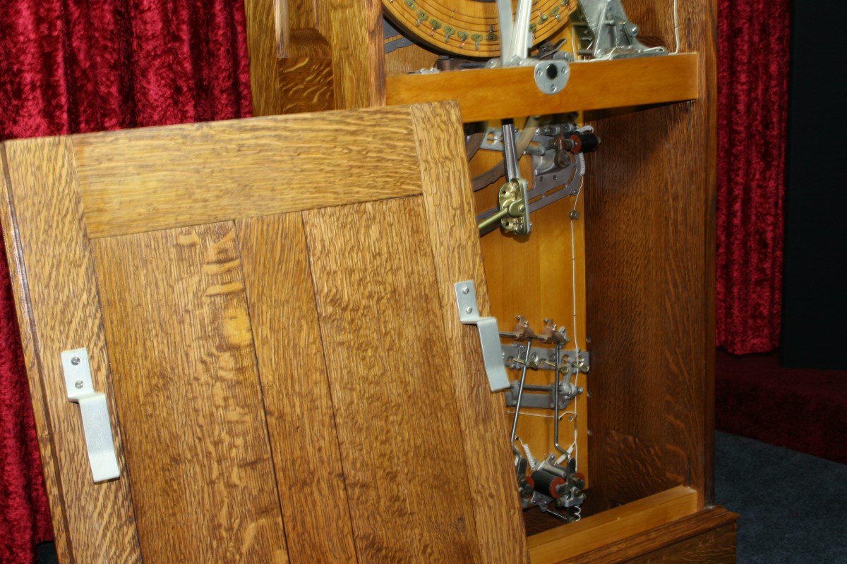
Simple Back Door Latches Hook Over Wood Crosspiece
Catch Grabs Actuator Arm – Prevents False Coin Release if Machine is Rocked
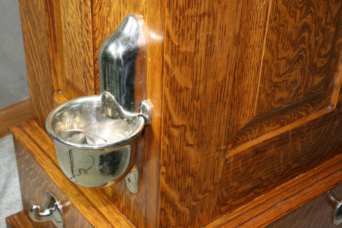
Coin Cup and Hooks Used to Tie Cabinet to Floor
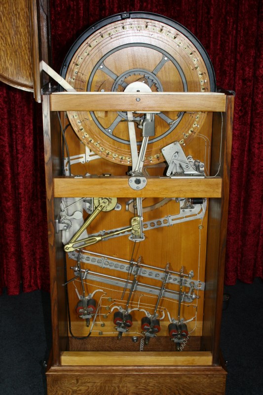
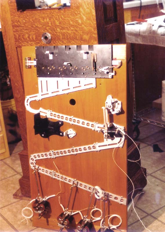
Mechanism of Completed Restoration
![]()