A Milling Machine Spindle Camera
Modified Webcam Provides Tool’s-Eye View of Work

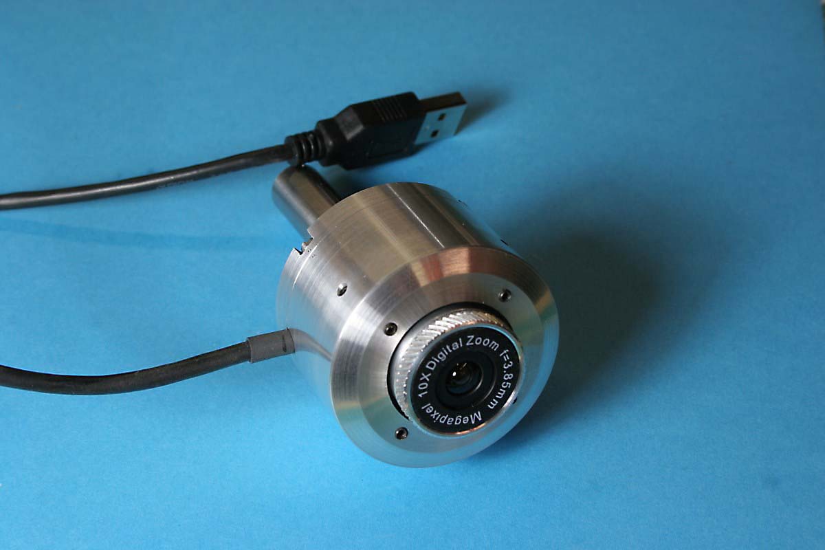
Camera Mounts in a 1/2″ Collet In Milling Machine Spindle
It’s been a busy home-project summer (as in home-maintenance) but there have been a few shop projects that I have not had time to write about. One of these projects was the fabrication of a video camera that could be swapped for the milling cutter and used to precisely place a target under the cutter visually rather than by the numbers.
Sometime last spring I got the urge to buy and perform a CNC conversion on a small Grizzly G0704 milling machine. Before beginning this project I knew there would be a need to machine stepper-motor adapters and other hardware components to a higher degree of precision and accuracy than I routinely care about. And since many of the parts would have to mate with the machine castings, I needed a way to measure dimensions and hole spacings more accurately than by simply using a dial caliper.
Many other DIYers have built spindle cameras (I’m calling this one a mill-cam from here on), and a web search turned up several different approaches. I incorporated many of their ideas into this design and added a few of my own, including the ability to adjust the tilt the vertical axis of the camera.
I went ahead and built this without thinking too much about how it would ultimately be used. There was the expectation that it would be fun to play with and useful in some specific applications, but I had no idea how immediately useful and indispensable it would become. The mill-cam has also been used as a lathe-cam a few times too – mounted in a tailstock chuck it will give a magnified view of a workpiece being centered in a four-jaw chuck.
How It Is Used
I can think of at least three ways of using the mill-cam as a measuring or positioning aid, and there are no doubt many more. All of these will be aided by using the camera viewer function built into Mach3 , a popular CNC machine control software application offered by Newfangled Solutions, and a free Mach3 Camera Plugin by Klaus Dietz that adds crosshairs and other reference features to the camera view screen. Mach3 may be used in demo mode when serving as a webcam viewer; there is no need to purchase a license for this application. Please see the note pertaining to camera plugin resolutions at the end of this article.

Camera Plugin by K. Dietz for Use With Mach3 has Crosshairs, a Circle, and a Rectangle to Assist With Alignment
The three methods of positioning/measurement are:
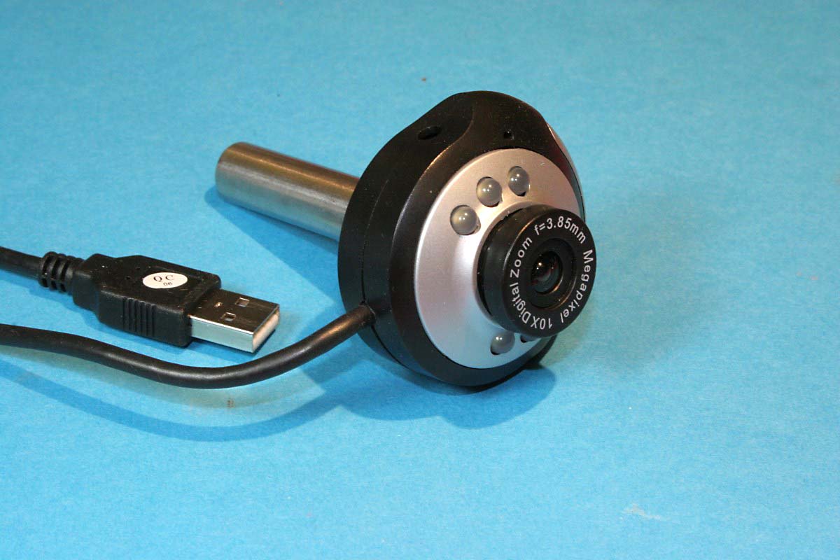
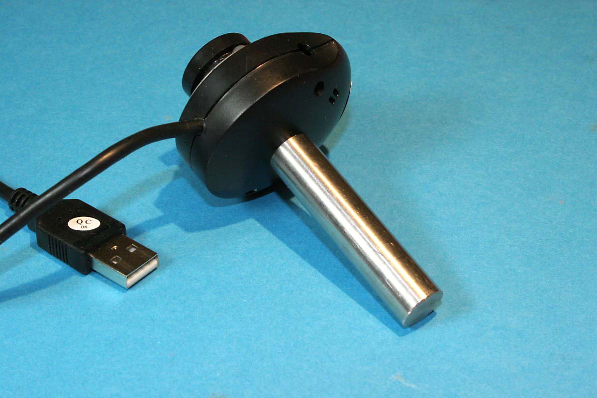
1) Relative Measurements: the camera is mounted in a spindle collet and used in conjunction with a digital readout (DRO) on the mill as a sort of optical comparator. This is extremely useful for accurately measuring hole layouts or other features on a fixed plane of a casting or previously machined part. The camera does NOT need to be aligned with the milling machine spindle as long as it remains in a fixed position throughout the measurement process. Simply adding a shaft to the back of a plastic-cased webcam can serve this function as long as it is reasonably rigid. Here is an example:
2) Absolute Measurements: with this method the end mill or drill chuck is removed from the milling machine and the mill-cam substituted. The target on the workpiece, whether an edge, a punch mark or a scribed mark is aligned with the image crosshairs, and then the camera is removed and again replaced with the cutter.
This method requires a design that allows the camera sensor be shifted slightly as required with respect to the spindle and locked in that position so that the image center and the center of the crosshairs represents the true center of the mill’s spindle. Once this is accomplished, the mill-cam can in many cases be used as a non-contact substitute for a dial test indicator, and it offers several advantages when dealing with imperfect surfaces that may be difficult to measure with a contact indicator.
Keeping the camera in alignment for absolute measurements requires some effort – the camera must be handled like an egg and checked periodically by manually rotating the camera through 360 degrees when mounted in the spindle to ensure that a point target remains centered.
3) Absolute Measurements with Offset: the mill-cam is permanently mounted to the milling machine quill at a fixed, known offset from the spindle center. The target is imaged, then the offset adjustment is made by moving the mill table to put the target under the cutter. It’s as close to real time monitoring as you will get, and you don’t need to swap the cutter and the mill-cam all of the time. The critical alignment requirements for the camera are the same as for 2) above, although the lateral and tilt (if used) adjustments can be built into the offset mount instead of around the image module itself, and also the camera should stay in alignment more easily without the need for frequent handling. NOTE: This method can ONLY be used if your milling machine has zero rotational play in the quill. Slop in the quill can allow changes in the angular relationship between the camera and the spindle axis. I think if I planned to use this method I would build a rigid camera mount that also incorporated a couple of preloaded bearings riding a vertical rail (mounted rigidly to the head casting) to provide that essential rotational stability. Alternatively you could avoid the quill mount altogether and just hang the camera rigidly on the head itself at a fixed offset from the spindle, but you lose the essential ability to quill-focus on a round-column mill drill. Knee mills or square-column mills with Z-axis ways would not have a problem.
A distinct advantage that a camera offers over a mechanical test indicator is that you have the ability to use your brain to instantly average the alignment to imperfect edges. A rough edge will appear as fluctuations on a dial indicator, but visually setting a crosshair line on the average of that same rough edge is a very fast process. The camera can differentiate between the surface chamfer of a hole or edge and the true hole diameter or true edge simply by using the quill feed to set the focus slightly deeper. A chatter mark or other defect from a milling cutter can be seen and ignored as an outlier when homing in on the optimum workpiece position.
Some have discussed the use of image scaling and using some type of on-screen graticule for making direct visual measurements rather than by moving and centering features on the screen and taking measurements using the DRO. I never pursued this because the lens does display significant fisheye and focus distortion at close ranges, and I’m not sure how linear the scaling would be over the full image. I chose to only use the center of the image as a valid reference point; the work is always moved to the center and nothing off that center is considered positionally valid.
Although I still do not have a handy location for my shop laptop that I use for viewing the camera, I find that I am using the mill-cam more and more and using my Mitutoyo test indicator less. Eventually I will have my CNC mill set up immediately adjacent to the manual mill-drilll and I expect to be able to use its computer and monitor for the mill-cam viewer.
Design
A webcam with the ability to be manually focused (rather than one that auto-focuses) at a very close range was necessary in order to achieve the high magnification required to resolve below .001″. Ideally the image module guts of the chosen webcam would be contained on a single squarish form-factor circuit board. In designing the housing for the image module, the image sensor of the camera module would need to be adjustable horizontally within the canister housing to allow precise alignment of the image center with the spindle center.
And although webcam lenses that focus by screwing in and out on plastic threads are fine for normal focal ranges, the focuser would have to be modified to be more stable at high magnifications, essentially removing any slop in the threads and the lens barrel.
The concept that most have followed to achieve these ends has been to mount the image module on a compact cylindrical base, and then suspend that base within a larger canister by four adjustment screws such that the image module can be aligned to the spindle center in the same way as a four-jaw lathe chuck centers a workpiece. Supplementing this I also added four adjustment screws to the bottom of the aluminum canister in order to tilt the plane on which the base rests, allowing the image sensor to be pointed exactly vertical to account for minor variations in the image board and lens assemblies.
Early on I toyed with the idea of a design where the USB cable connection to the camera was free to spin on bearings and the four connections to the image module were made through a custom slip-ring contact made from a circular printed circuit board and some type of adapted spring contacts from a connector. This would allow the camera to spin freely for alignment without taking the cable with it. Common sense took over, and I realized that I would simply limit my motions to 180 degrees either direction, and thankfully I haven’t yet absent-mindedly hit the motor switch with the camera mounted in the collet.
Choosing a Webcam and Making the Components
I got lucky when I searched for a webcam on Amazon. I came across the TECKNET C016 720p HD webcam for something like $14 with free shipping. It had manual focus with a very close focus range, and for that price it would be most definitely be worth a try.

I Bought Four of These From Amazon for $14 Each
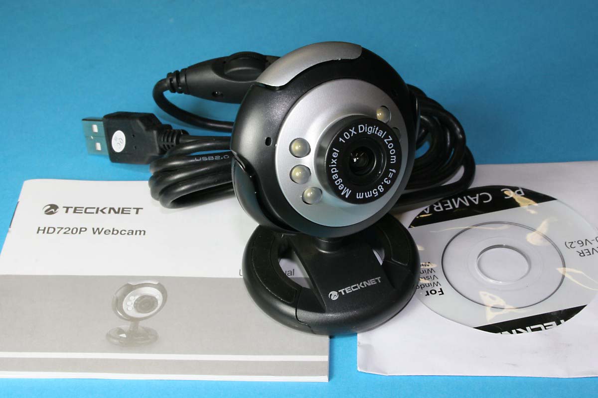
A 720p HD USB Webcam with 6 LEDs. Software Disk Included
As it turned out the camera was perfect for the application. The circuit board is small, image quality is very good, and even though the lens shows pincushion and focus distortion at very close range, it does seem to be of decent quality in the center of the field of view, which is all that really matters (I never attempt to use scaling). It also has six on-board dimmable LEDs, but I chose not to use them to keep the unit compact and also because I have dual adjustable worklights on my mill-drill already. I need to move my lights around so much to optimize the lighting angle under various conditions that I suspect that incorporating integral LEDs into a mill-cam may not be as universally useful as it might appear.
The webcam was disassembled and the image module was removed from the plastic case. The webcam has a pushbutton used for still captures which I removed. The LEDs were also removed from the circuit board.
The cylindrical base for the image module mount was made from acetal (Delrin). The plastic would eliminate worries about any part of the circuit board shorting and would also provide a silky smooth bore for the knurled aluminum lens barrel that the plastic lens mount would be pressed into. The plastic threads of the lens focuser are still used, but the concentricity of the lens is maintained by the close fit of the aluminum lens barrel in the acetal base.
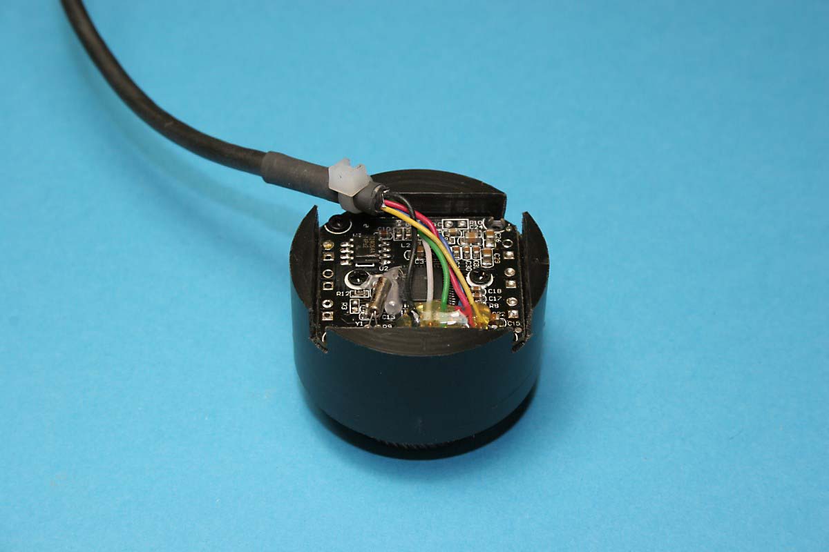
Cylindrical Acetal Base Holds the Image Module
Knurled Aluminum Lens Barrel is Smooth Friction Fit in Acetal Base
The canister and cover were machined from aluminum, and the shaft was machined from 12L14 with a taper on one end that matches the hole taper in the aluminum cover.
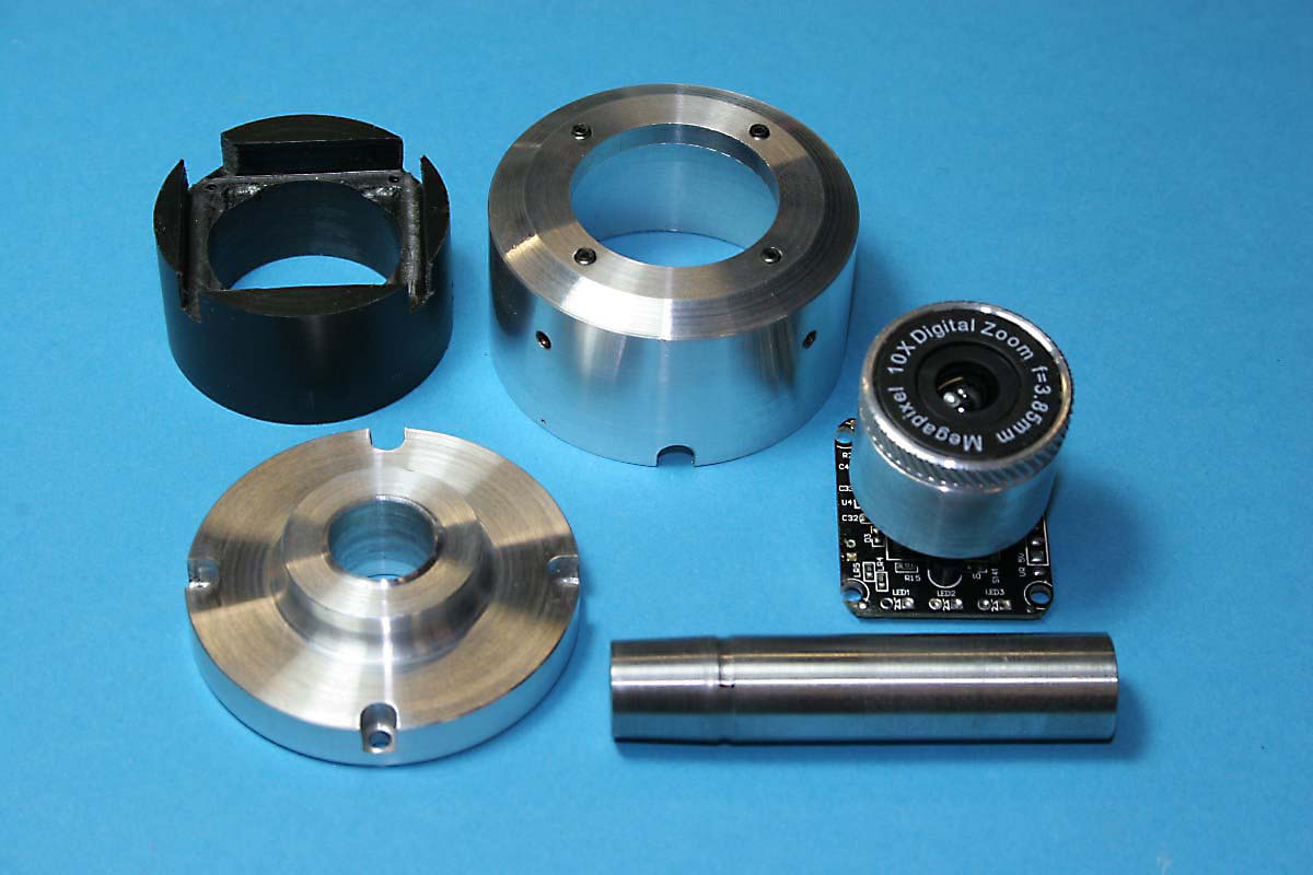
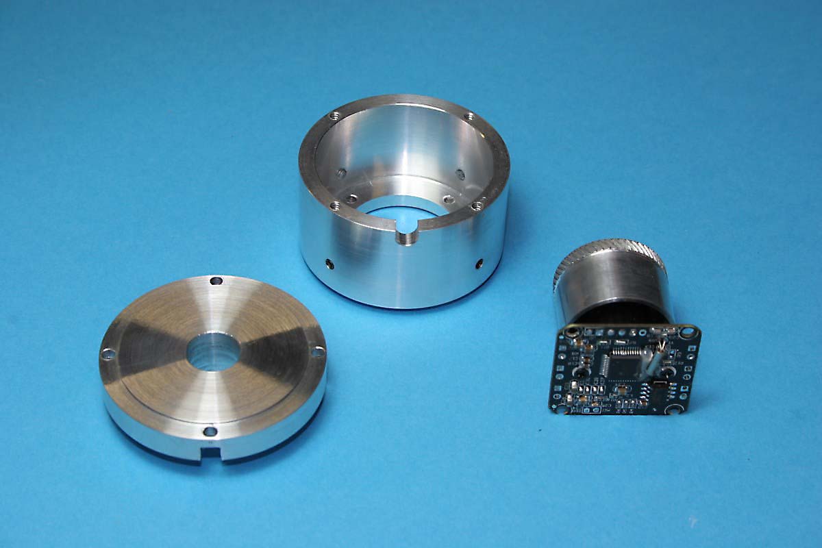
CW From Top Left: Acetal Base, Canister, Image Module, Spindle Shaft, Cover
Inside Views of Canister and Cover
The canister bore is large enough to leave about a .050″ gap around the acetal base because I did not know the exact location of the image sensor on the board, and there was a good chance it was not in the geometric center.
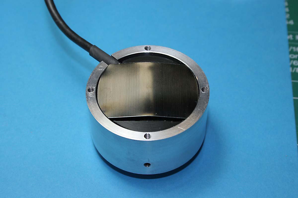
Flat Steel Spring Presses Acetal Base Downward
A piece of blue spring steel was bent to firmly press the acetal base and image module toward the four set screws on the lens-end of the canister. These four screws adjust the tilt of the image module so that it can be conceivably set to be perfectly perpendicular to the spindle axis. Three screws would provide full support but four makes it easier to separately tilt the X and Y axes at the expense of having to make sure that all four screws actually apply pressure. Three will take the load and one screw will slack off until you find it and tighten it a bit.
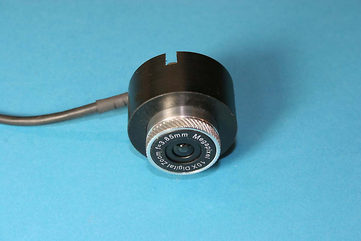
Here are a couple views of the completed Mill-Cam assembly:

Things You learn After It’s Too Late
I had envisioned a mill-cam that I would use for both micro and macro views, allowing me to swiftly spin the focuser to the desired field of view and line up to an edge or the center of a hole. I soon learned that this would not be the case. The first thing I noticed was the amount of image wobble present with each rotation of the focuser. The focuser barrel was tight and repeatable, but the lens was clearly not concentric or perfectly perpendicular to the rotation axis in the plastic housing that was pressed into the precision knurled focuser barrel. This meant that any attempt to absolutely align the image center (for using crosshairs as described earlier) with the center of the spindle shaft would only be valid it the focuser barrel was left untouched. Since adjustment of the alignment, like adjusting a four-jaw chuck, is not a particularly fun operation, I have settled into using the camera at a fixed magnification and a fixed focal range.
This unfortunate fact also lessens the need to build the tilting capability into the design. The intent was to ensure that a point feature at the center of the screen (punch mark or scribed lines) would remain in a fixed position as the magnification and focal plane changed, meaning that the camera was looking straight down and not off at a slight vertical angle. But if you are forced to use the lens at a fixed magnification and fixed focal plane because of lens/sensor chip geometry errors, the need to have a perfectly vertical view is lessened. Certainly the object in view should not drift in any direction over the practical focal range, but if an edge has shifted when you are well out of focus, it doesn’t matter. In short, although little effort is needed to add the tilt set-screws, don’t expect perfection and don’t bother if you can’t fit them in.
The lens position actually changes the focus, but magnification is directly related to the focal distance (close focus = high magnification and vice versa). Since the milling machine’s quill feed provides a more convenient means of focusing than turning the lens barrel, I usually just leave the mill-cam aligned and calibrated on close focus with the ability to resolve distances easily less than .001″. This translates to a focal distance of less than .200″ which can be a problem if viewing features that are recessed and surrounded by objects that protrude into the space required by the mill-cam body (consider compactness when designing your unit).
One more note: the lens barrel has a thin square glass IR filter glued into the end opposite the lens intended to reduce the camera’s inherent sensitivity to invisible infrared. I thought that removing it might improve the low light capability a bit so I tried to pop it loose. It did not come out intact, so I just broke it apart and cleaned out all of the shards of glass, When I tested the camera again it seemed like the shadow detail was improved slightly, but what I noticed the most was the color shift. The webcam’s original color balance was quite good, but with the IR filter removed everything now had a red/purple tint – even gray metal had a slight red cast. For this application it doesn’t matter, but I don’t think there is any real benefit to even spending the three minutes that it takes to remove the filter.
Adjustment/Calibration
This process can be summed up as follows: simple in concept, confusing as hell to perform. I have found that I no longer try to think about where I am or anticipate what an adjustment will do. I just work reactively, making a small adjustment and observing whether it is in the right direction and reversing if it is not.
Part of the reason for the confusion is the fact that aligning the image module within the mill-cam body requires manual rotation of the milling machine spindle 180 degrees and +90 to -90 degrees from its normal upright position, and consequently up and down and left and right are constantly inverting or reversing on your screen.
Another part of the confusion comes from the fact that the reference feature that you are viewing also needs to be precisely centered on the milling machine’s spindle axis. So when you start off you will need to first jockey the x-y table to center the target under the spindle, and then adjust and the mill-cam centering screws. The results may not be what you expect at first.
Three things to remember for alignment:
1) If the mill-cam image module is centered correctly within the body but the reference feature is not centered under the spindle, the reference feature will trace out a circle as the mill-cam and spindle are rotated through 360 degrees.
2) If the reference feature IS centered under the spindle but the mill-cam image module is not aligned, the reference feature will remain fixed at some point on the screen other than the center (if within viewing range) and everything will rotate around that point.
3) Use the x-y table to adjust the reference feature to achieve a stationary point somewhere on the screen as the spindle is rotated. THEN adjust the four side setscrews on the mill-cam body to move that stationary reference point to the center of your image.
A Few Sample Images
For some reason my screen capture utility was conflicting with Mach3 or the camera plugin and I was unable to obtain any screen captures of the mill-cam viewer. I resorted to snapping some photos of my laptop screen with various items under the camera to give an idea of the scale and field of view. The actual screen images seem somewhat better than the photos would indicate and in the region of sharpest focus they do indeed appear as if they could have the 720p HD resolution as advertised.
Again keep in mind that the magnification and field of view can be varied to suit your own tastes. This is where I keep my camera focused and aligned, and at these settings I can see visual changes well before my .0005″ digital scales register a change.
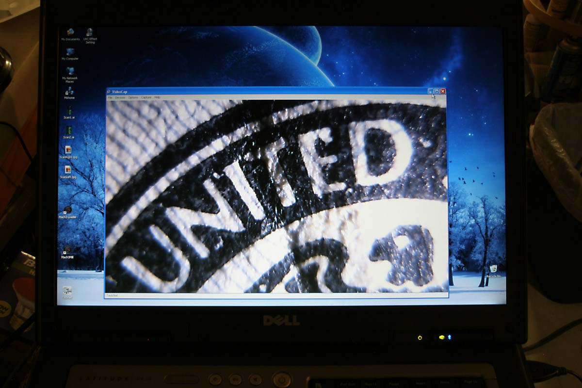
Paper Currency #1
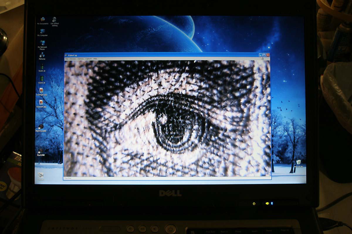
Paper Currency #2
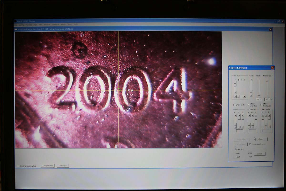
Date on a Penny

Millimeter Marks on a Ruler

Etched Mark on Stainless Ruler
A Note Regarding Use of the Camera Plugin
I have had greater success using the V2.14c camera plugin (PluginCameraV2.14.exe) by K. Dietz than with the recent beta release V3.00. Although the V2.14c plugin does display and report an image resolution of 1280 x 720 with the TeckNet camera, this resolution is does not make an appearance in the pulldown menu of available resolutions. The three available image resolutions are limited to a maximum of 640 x 480, and if you should choose one of the lower resolutions there seems to be no way of getting back to 1280 x 720 short of uninstalling and reinstalling the plugin.
Although I only tried it once, V3.00 does not seem to recognize the higher resolution at all and defaults to a lower resolution and smaller display image.
It is also necessary to activate the plugin-in within Mach3 after installation by going to Config>Config Plugins and changing the red X in the Enabled column beside the WebCamPlugin – Version -XXX in to a green check mark. It will then appear as one of the available choices under the Plugin Control header.
![]()