Homebuilt Video Camera Stabilizer
Preventing the Blair Witch Jitters
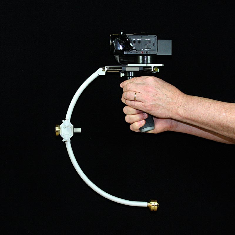
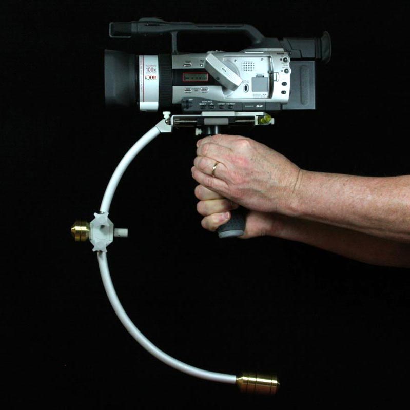
Homebuilt Stabilizer with Canon HF-M301 Camcorder
One downside to the ultra-miniaturization camcorders and other video recording devices is the increased difficulty in holding the camera steady. The earliest camcorders, despite their awful video quality by today’s standards, did from a pure stability standpoint have the inherent advantage of larger size and mass going for them. Resting a heavy camera on the shoulder tames some of the worst jitters, but palm-sized cameras simply aren’t large enough in any axis to stabilize against the body.
Using even the simplest video stabilizer with a camcorder can result in a large improvement in picture stability. Optical and digital stabilization in camcorders can only fix a limited amount of camera mishandling – it pays to have a stable platform to start with. Learning to balance and operate a stabilizer effectively will take a fair amount of practice, but even if your movements do initially wallow around a bit when tilting and panning, the worst jitters will be gone almost from the moment you start using it.
I probably shouldn’t start off trying to explain physics behind video stabilizers – it’s a topic that is well-covered elsewhere, and you may want to skip this beginning part if you are more interested in the project. The concepts and terms mentioned here are really just first-year physics, and most passive inertial stabilizers work the same way and use these same principles.
The Homebuilt Stabilizer Group is a forum dedicated to the discussion of both commercial and homebuilt stabilization systems, including design, fabrication, and handling techniques. DIY camera stabilization is truly within the reach of anyone. Effective homebuilt systems have been made with galvanized pipe and barbell weights, while others are beautifully crafted articulated systems rivaling commercial systems that cost thousands.
The Basics of Stabilization
If you want to consider portable camera stabilization systems – those that are self-contained and supported entirely by the camera operator – there are at least two main types.
- The first is a brace type that couples the camera to the operator’s body, usually resting on one or two shoulders and sometimes the chest, and it relies on the stability and fluidity of body movements to stabilize motions. These are generally simple and relatively lightweight, and effective for shots where the operator is standing still or pivoting. Shoulder movements when walking and running are not isolated, but there are still many benefits over using a hand-held camera.
- A second type, the type we are discussing here, is an inertial stabilizer that attempts to isolate all axes of rotation of the camera platform from the operator’s body, increase the moment of inertia of the platform, and decouple some translational (X,Y, and Z) movements as well.
With this type of stabilizer the camera is counterbalanced (sometimes using accessory equipment or additional weights) to move the system’s center of mass (center of gravity) to a point outside of the camera’s body. This will be the point at which the operator supports the system and supplies steering inputs.
Located very close to this center of mass is a low-friction gimbal that permits rotation in all axes, and the weight of the entire camera platform is supported at the gimbal. This support for lightweight systems can be the hand and arm, but for heavier systems support comes from a spring-balanced articulated arm attached to a rigid body harness. The articulated arm and harness use the back and shoulders to fully support the weight of the camera system and allow translation movements in all axes; the arm and hand are only used for guiding the floating camera system.
Simply hanging a counterbalance weight under a camera platform does not make a very effective portable video stabilizer. It can help minimize shakiness, but if it is not supported at the correct location any horizontal movements will result in a swinging pendulum effect. A video stabilizer intended to be tolerant of movement and accelerations must be supported theoretically at its center of mass.
A simple experiment will demonstrate this:
If you grab a sledgehammer vertically with two fingers at the middle of its handle (head end down) and shake it rapidly left and right, the upper end of the handle will move more than the head. If an imaginary camera (of zero mass) was mounted on the top end, any attempt to start walking and then stop would be accompanied by camera rotations from the swinging pendulum.
But now instead hold the handle horizontally and find the balance point on the handle, very close to the head. This is the center of mass. Now grip the handle loosely in the same vertical orientation with two fingers at that point, and rapidly shake it left and right again. This time instead of swinging and rotating, it will remain almost perfectly vertical as it shifts left and right; you are applying an accelerating force at the center of mass, and it results in movement without rotation. In this case the imaginary camera at the top end of the handle would have a stable image with no roll or tilt.
In practice the support point will be tuned to be slightly above the center of mass; this will force the camera platform to return, albeit slowly, to an upright level state.
A camera, accessories and batteries, counterweights, and the mechanical structure of the stabilizer considered as a group will have a total mass equal to the sum of the individual masses, and a center of mass which is a single unique point located somewhere within the physical boundaries of the group of items. The center of mass is the only point in this group at which a force can be applied from any direction without imparting a rotation to the group. This characteristic is very important for a video stabilizer. The operator must be able to accelerate in any direction and stop suddenly without imparting any unintentional rotation to the camera.
Camera stabilization is all about the physics of inertia. Simply adding concentrated mass directly to a camera will increase its inertia; more force will be required to accelerate it in the X, Y, or Z axes than would be required if it did not have the mass attached. In some systems this can be beneficial for camera stabilization, but is not necessarily the most bang for the buck. Or in this case, it does not the greatest image stabilization for each kilogram (or pound) of added weight.
A handheld camera’s picture stability is most affected by rotational motions; your subject appears to be jittering up and down, left and right, or rolling. These are primarily caused by rotations of the camera.
On the other hand, pure translation movements, without any camera rotation (like a vertical pedestal move), are often less noticeable in typical distance shots and will become invisible as your subject’s distance approaches infinity.
Going back to the example of the concentrated mass attached the camera, this was described as a way of increasing its inertia. Increased inertia means that more force is required to start the camera moving in a straight line or to slow it down. But this concentrated mass does little to stabilize the rotations of the camera – in fact a pinpoint mass located at the center of mass of the camera has no stabilizing effect on rotation.
An effective stabilizer can be made by concentrating on achieving rotational stabilization first; translational stabilization will often occur as a side benefit. This means that the moment of inertia of the camera platform must be increased in the axes that must be stabilized. There also may be a desire to have different stabilization in each axis of rotation:
- Horizontal Pan should be lightly stabilized. This very common move should be smooth but allow rapid movements without overshoot.
- Vertical Tilt can be heavily stabilized unless you need to follow bouncing balls
- Roll can be the most stable axis of all, unless you are looking for Twilight Zone or otherworldly effects.
Moment of Inertia is a measure of how much torque is required to rotationally accelerate a body. Compare this with Inertia, which is a measure of how much force is required to linearly accelerate a body.
Moment of Inertia (I) is defined as follows:
I = m * r2 where m is mass and r is the distance (radius) of the mass from the center of rotation
Note that Moment of Inertia (I) increases linearly with mass, but increases with the square of distance from the rotation point. This means that doubling the mass will double the moment of inertia, but you have also doubled the weight that you have to haul around. On the other hand, doubling the spacing between the masses you already have (like camera and monitor, for example) will quadruple the moment of inertia without adding any mass or weight to the system at all.
An effective stabilizer will have a high moment of inertia for tilts and rolls, and a low or easily adjustable moment of inertia for pans. If your camera system is simple and lightweight (camcorder only, say) you will need to add weights in a manner that increase the moment of inertia as much as possible for the added weight. This generally means putting the camcorder at the top of a pole with a gimbal located a convenient distance below, and counterbalancing the weight of the camcorder with extra weight at the bottom of the pole.
The weight of this simple counterbalanced-camera-on-a-pole is supported at the gimbal (the balance point) or more typically slightly above. This system will provide minimal resistance to horizontal pans, but tilt and roll will both be stabilized because the masses of the camcorder and counterweight are both at a non-zero distance from the center of rotation for those two movements, and hence contribute to increasing moment of inertia.
In a hand-held system, the arm must bear all of the weight. Any added weights must be thoughtfully placed so as to maximize the tilt and roll moments of inertia. Weights are not added in a hand-held system simply to increase translation inertia.
In more complex and heavy systems, cameras, monitors, and batteries are placed at distances from the gimbal point to maximize their effectiveness in contributing to moment of inertia, but these masses will contribute to translational inertia as well, regardless of where they are placed with respect to axes of rotation. In heavy systems the entire weight is supported by the articulated arm and harness, and the added overall mass will contribute to the translational stability of the camera, allowing the operator to walk or run with little effect on the track of the camera.
There are demos of a camera operators wearing arm/harness stabilization systems that are hopping up and down while the camera platform remains motionless.
Note: using a mechanical stabilizer along with the camcorder’s electronic stabilization can result in undesirable effects, as is often the case with using a pan and tilt head on a tripod. Try turning off the electronic stabilization.
The Homebuilt Stabilizer Project
If you’ve studied video camera stabilizers at all, it should be pretty clear where this design came from, although I have never had a chance to handle or use the original. I liked this design because of its compact size and the fact that the handle grip was located directly under the gimbal, which seemed like it would be more comfortable to hold than a design with an offset handle. The curved balancing arm circles around the handgrip to locate the counterweight opposite the camera where it needs to be.
Although the version I made here works as it should, this design is moderately difficult to set up quickly. I originally used it (and sometimes still do) with a Canon GL2 camera, but now we also have small Canon HD camcorder and a Canon 7D DSLR, and each has its own use at various times. Swapping around is not fun.
The main thing I do not like with this design is the fact that the main counterweight sweeps in an arc as it is adjusted up and down. A counterweight on a pole stabilizer would generally be sliding directly toward or away from the camera and gimbal to set the camera balance. On the stabilizer discussed here, the front knob adjustment that pulls the lower counterweight upward complicates that effect with a rearward movement. Instead of just balancing the camera you now have to shift the camera forward or backward on the platform.
If I had to do it over again I would try to keep each balance adjustment pure, without any interaction. Anyway it is what it is, and here it is…
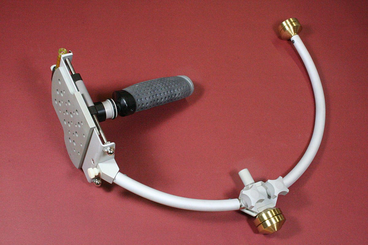
Completed Stabilizer Assembly
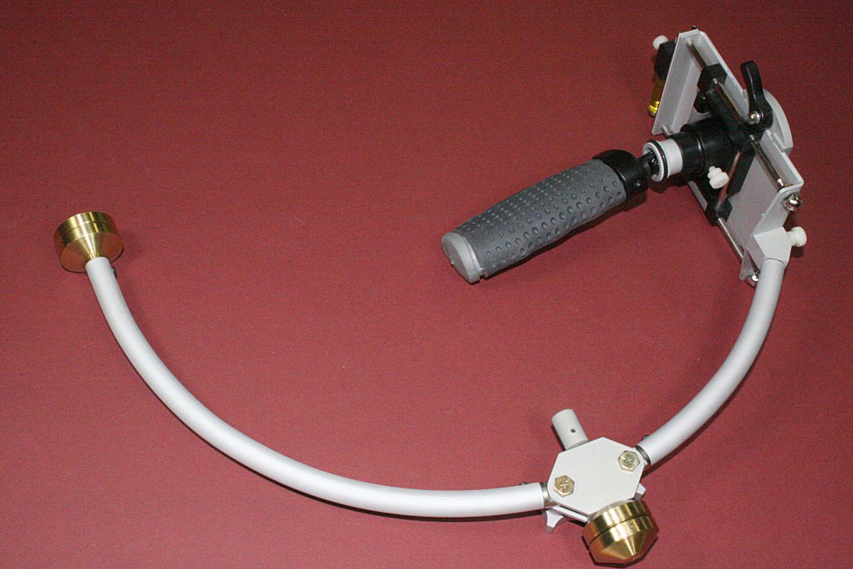
Another View
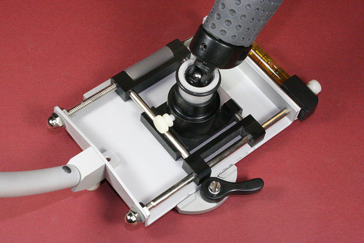
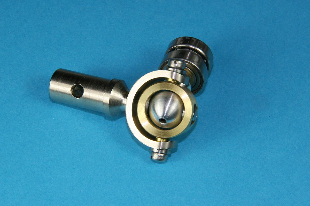
Gimbal and Camera Platform
(NOTE: The plastic gimbal shown here has been replaced with an improved ball bearing gimbal)
The first challenge was to find a suitable gimbal bearing that allowed rotation in any axis. It had to be small and although I wanted to use ball bearings to minimize friction and any end play. At the time I could not find any reasonably priced bearings in an extremely small size, nor was my machining capability up to making something that small. It was actually after this project that I decided to put digital scales on my mill-drill, which has changed my outlook on everything.
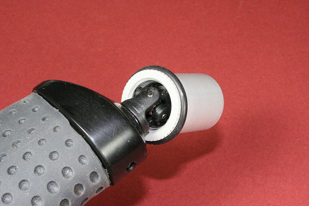
RC Truck Universal Used for Gimbal
I ended up choosing to use an RC truck universal joint from the hobby shop for the gimbal. I thought I was being clever at the time but I see now that this is all over the discussion groups and YouTube, and rightly so. It is compact, made of plastic and steel, and sufficiently low-friction. The joint would permit movement in two axes of rotation, and the third axis (the vertical axis for pans) was taken care of with a larger bearing pressed an aluminum cup that houses the gimbal.
This cup is designed to house all of the gimbal bearings and provide a steering ring encircling the gimbal centerline. This is the ring that is manipulated by the free hand to steer the camera platform while operating the camera. The ring was originally knurled, but I later grooved it to hold an O-ring. This is somewhat different from the gimbal design of the commercial model, but out of everything this is one part I am very happy with. The O-ring and the cup diameter have just the right feel when trying to steer the platform.
The cup inserts into a hollow boss of a machined black acetal plate that is mounted on adjustable cross slides on the bottom of the camera platform. The cup has a threaded hole in the top which screws onto a threaded stud inside the boss. This allows the height of plate above the gimbal to be adjusted by rotating the aluminum cup in the boss to the right depth, and locking it with a white nylon thumbscrew. This is handy for quick adjustment of the stabilizer’s neutral stability, moving the center of mass of the entire camera and platform assembly at or slightly below the gimbal centerline.
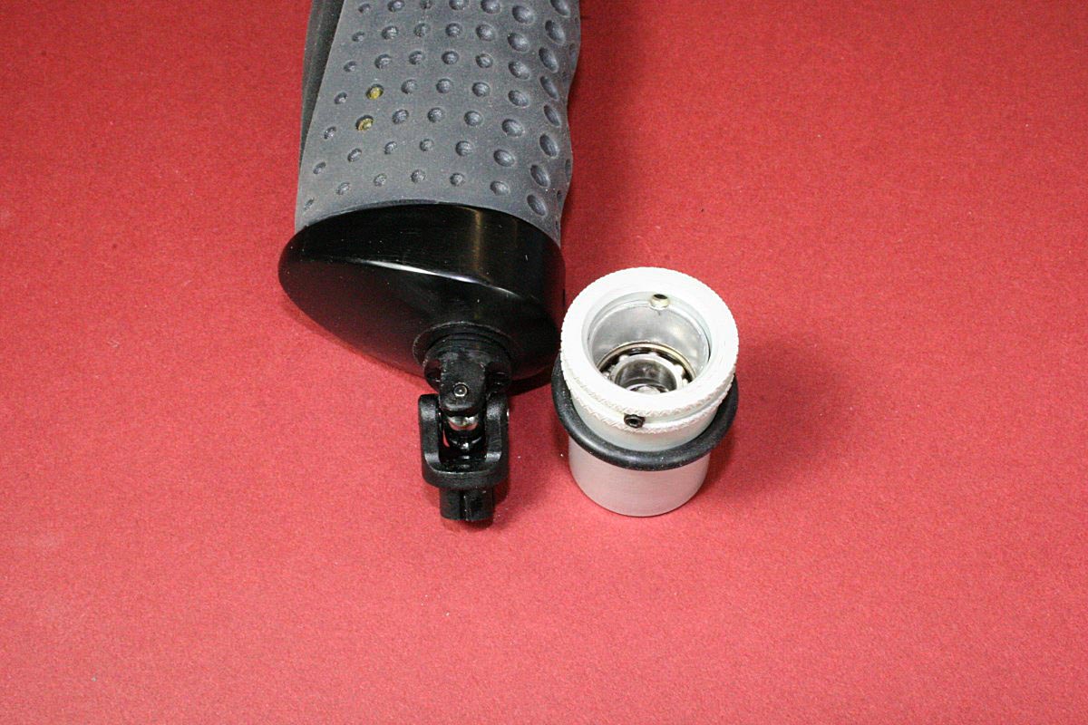
Gimbal and Cup – Note Ball Bearing Inside Cup
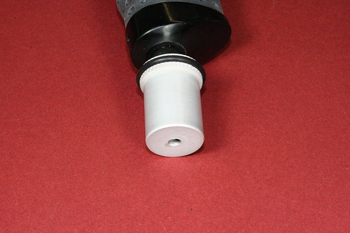
Threaded Hole in Top of Cup Allows Height Adjustment
Cup Screws Into Threaded Stud Inside Boss
White Nylon Thumb Screw Locks Cup in Position
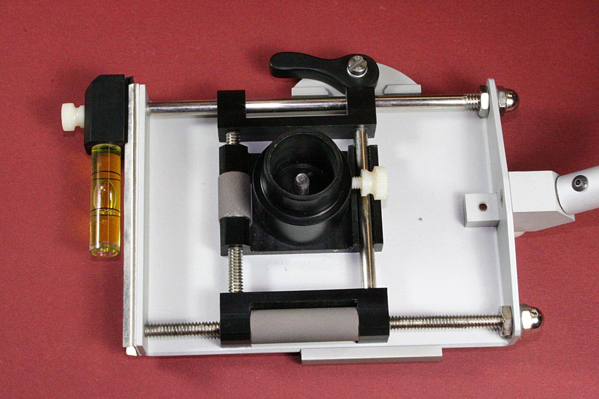
The base of the camera platform is made of .080″ aluminum with the ends bent at right angles as shown. The black acetal plate with the boss is held to the bottom of the camera platform by a dual-axis cross slide made of acetal, threaded steel rods, and smooth polished steel rods. Two knurled cylinders are threaded internally and allow the plastic boss plate to be moved along both the long and short axes of the camera platform.
These adjustments that I copied from the original design allow the platform’s center of mass to be moved laterally and fore and aft about the gimbal pivot point.
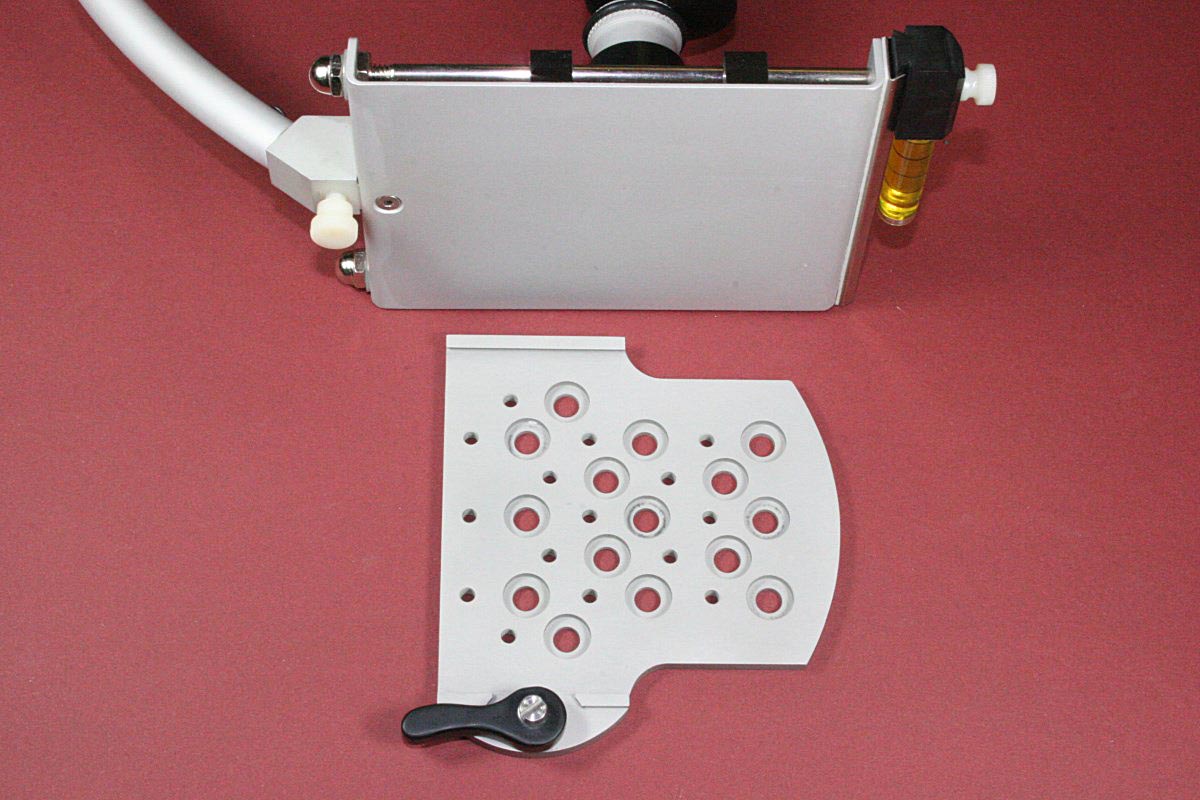
Drilled Camera Adapter Plate – Upper Edge is Dovetailed
One long edge of the formed aluminum camera platform is beveled at an angle to match a dovetailed recess in the bottom of the thicker camera adapter plate. This plate has multiple holes machined in it to allow for different mounting positions for different cameras. The plate has an acetal locking lever on one side to lock in to the camera platform.
To mount the adapter plate, the dovetailed edge is placed over the beveled edge of the camera platform and the adapter plate rotated into contact with the camera platform. Once moved to the correct for/aft position, the lever is latched, locking the camera adapter plate securely to the camera platform.
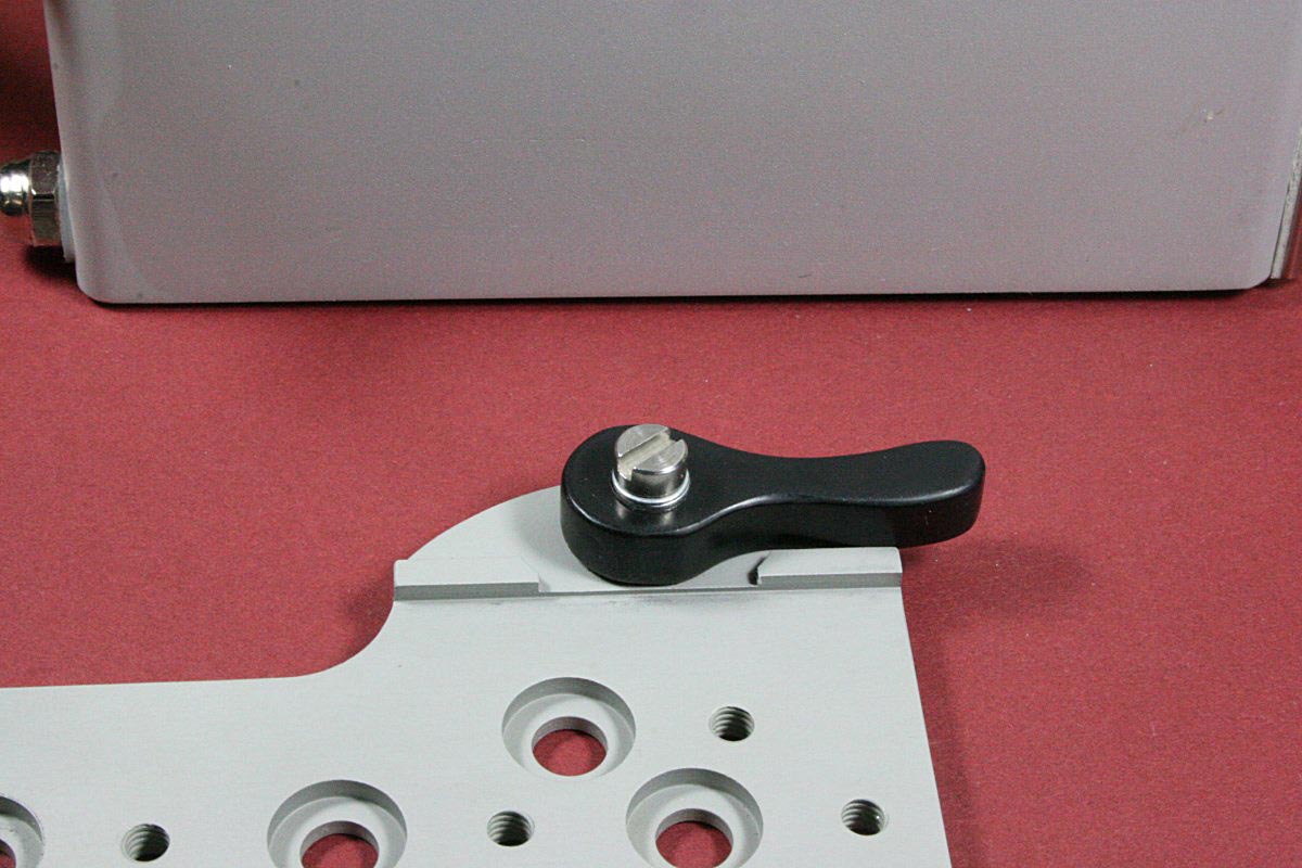
Adapter Plate Locking Lever – This Edge is Not Dovetailed
Adapter Plate Locked to Camera Platform
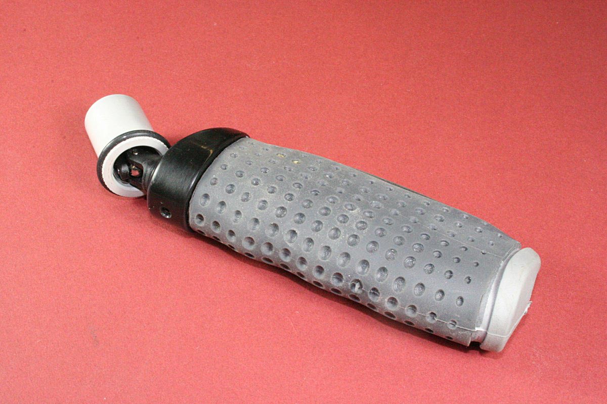
Oval Handgrip With Acetal Plastic Endcap
The core of the handle grip was made from a piece of 3/8″ diameter aluminum rod bent into a tight “U” shape. The two open ends of the shaped rod insert into holes drilled in the bottom of a teardrop shaped piece of acetal that forms the top end cap of the handle and a mount for the gimbal. A rubber bicycle grip was stretched over the aluminum rods, which gives it a very comfortable oval cross-section for the hand. This was intentional – I had tried a standard round tube handle and found this to be much more comfortable for extended periods. The acetal end cap was shaped to match the contour of the rubber grip and polished to look more like a molded part.
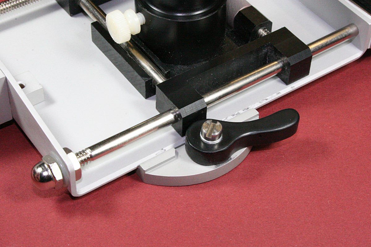
The bubble level was an afterthought. It helps with the balancing process and I sometimes glance at it on the fly. A guide strip of stainless steel attached to the rear of the camera platform was bent on a brake to match a dovetail cut on the acetal block holding the bubble vial. The nylon thumbscrew locks the level anywhere along the guide.
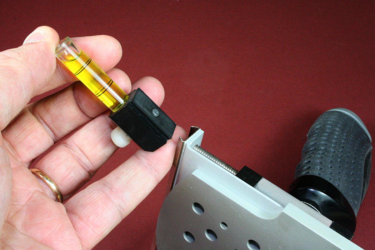
Dovetails Self-Align the Bubble Level as Thumbscrew is Tightened
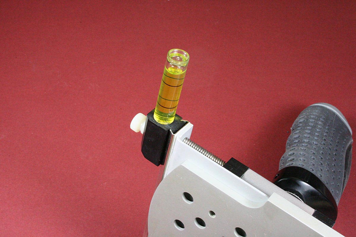
Level Can Be Extended to Clear Larger Camera Bodies
The Adjustable Counterweight Balancing Arm
The two curved segments of the balancing arm were made by bending a single long piece of 1/2″ OD aluminum tubing around a hardwood form. The radius of the form needed to be smaller than the final tubing radius because of the spring back, but accuracy on this part was not important. To prevent the tubing from flattening or kinking, a concave semicircular groove was routed in the edge of the hardwood form with a 1/4″ radius bit. This matched the tubing diameter and worked like a conduit bender to prevent any widening of the tubing as it was bent.
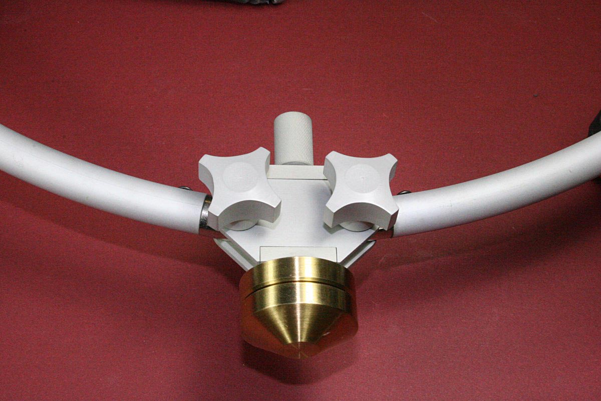
Knurled Knob Changes Angle of Counterweight Arms
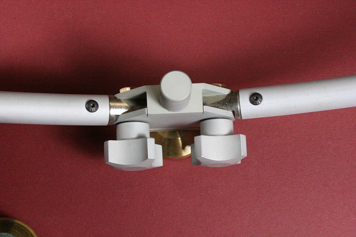
Knobs Securely Clamp the Counterweight Arms After Adjustment
The adjustable joint in the middle of the counterweight arm was a challenge to design and machine. Tolerances had to be tight and the mechanics robust enough to tolerate the high forces that the delicate parts would encounter if the joint was stressed while not in a locked-down state. The design I came up with seems to be strong and it adjusts well, but the stabilizer cannot be used without the locking knobs securely tightened.
Steel Ends Are Pinned to the Edges of Brass Block
Steel inserts were machined to fit in the ends of the curved tubes. The sides were machined flat and the centers were slotted. The pivot holes were bored to fit with minimum clearance of the shoulders of 3/16″ AN aircraft bolts.
Edges of a flat rectangle of brass were machined to fit into the slots machined in the centers of the steel inserts. The brass piece was drilled and tapped edgewise to move along the threaded rod that rotates with the knurled adjustment knob.
The housing for the joint was made in two parts as shown. One part has bosses to support the threaded rod at each end, and the other is a floating flat plate that is free to clamp the steel inserts when the knobs are tightened.
The knobs were machined from bar stock and steel inserts were pressed in – I wanted to be able to tighten these securely and repeatedly without fear of losing the threads.
The stackable brass weight at this joint appears to be there for the purpose of adding some extra damping to the z-axis (pan axis) of the stabilizer. On a larger system this may not be necessary, but panning on a lightweight camcorder on a light, hand-held stabilizer might be a little to twitchy without it. This weight increases the z-axis moment of inertia, but any changes to this weight will require rebalancing everything – another part of this design that I do not care for.
The brass weights can be cascaded together to optimize the weight for various size cameras. For the bottom counterweight I prefer to use as little weight as possible by keeping the adjustable counterweight arm as wide open as possible. When the arm is adjusted upward the counterweight can get bumped by my forearm.
A Few Words About Static Balancing
Very few words.
A neutrally balanced camera stabilizer will remain in any set position with no (or very little) drift. Inverted, sideways, camera pointing up or down – any position – will hold. This is generally NOT where you want to operate it. Once neutral balance is set, there is usually an adjustment that will allow the entire stabilizer center of mass to be lowered with respect to the gimbal point. On the homebuilt stabilizer described here that adjustment is made by threading the aluminum cup that houses the gimbal deeper into the plastic boss on the base of the camera platform.
After this adjustment is set correctly the stabilizer should slowly return to an upright level position from any starting orientation, but it should do so without any spurious rotations. The rate at which this return to normal occurs is up to the operator – the price of setting balance for improved self-leveling is an increased chance of drift with sudden accelerations.
And a Few Words About Aerodynamic Balancing
Attempting to use a stabilizer in a breeze or from an open vehicle will be problematic. A stabilizer system may be statically balanced in still air, but in a breeze there will probably be unbalanced forces above and below the gimbal point due to different aerodynamic drags. For example, a compact counterweight at the end of the balancing arm will have less drag than a monitor screen above the gimbal on the camera platform. The aerodynamically-induced torque at the gimbal is a function not only of the forces but of distance of those forces from the gimbal as well – a sail of a given size will have more effect at the end of a long arm than will a short one.
It is possible to experimentally arrive at a statically balanced stabilizer that is reasonably balanced aerodynamically. Lightweight styrofoam balls will have a drag that is independent of wind direction. A foam ball (whose size is determined experimentally) mounted either above or below the gimbal point (depending on the direction of your wind-induced drift) can help keep the stabilizer balanced in a breeze. The mass of the foam ball at its chosen location must of course be balanced out statically.
***Updates – An Improved Gimbal and an Anti-Roll Pendulum***
Limitations of the Plastic Gimbal
The plastic gimbal described earlier is quite serviceable but it does have some problems. Side play between the gimbal ball and the plastic yokes can allow the axis of the upper shaft to shift slightly and throw off the balance. Winding and tying off a couple of turns of Glide dental floss in the gaps between the ball and the forks on each of the four shafts would prevent the ball from shifting in the forks without adding much friction at all, but it would still loosen over time.
Another problem with the plastic gimbal was the limited range of motion – not normally a problem for roll, but for low camera positions (where your wrist wants to hold the grip at an angle) it would run out of back-tilt range. I decided that it was time to make a better gimbal.
An Improved Ball Bearing Metal Gimbal
Close Up of the Metal Gimbal in Use. The O-Ring is the Steering Grip
I had a bunch of small ball bearings left over from my RC helicopter flying days, so I designed a new metal gimbal around them. The bearings were 7mm OD x 4mm ID x 2.5mm wide, although even smaller bearings could have been used if I had been willing to order some.
It was a given that a metal gimbal would be larger than the plastic one and as such the camera platform would have to be a little higher (assuming that the same bearing cup was to be used above it), which would also require more counterweight and a greater overall weight. The single bearing in the cup (this is the bearing that allows the panning movement) would be upgraded to dual bearings at the same time to further eliminate any slop in panning rotation axis.
This gimbal design can swing nearly 90 degrees either way in one axis, but the other axis is limited to approximately 45 degrees either way before the ends of the handle yoke bump into the bearing cup. The gimbal was oriented on the hand grip to allow the maximum range of motion for tilt and the axis of rotation that was limited was used for roll. I never have a need to roll very much, and the added tilt range would eliminate any of the problems encountered in the past when trying to operated the stabilizer low to the ground without stooping.
All of the Parts for the Metal Ball-Bearing Gimbal
All of the parts for the metal gimbal can be seen in the picture. The outer fork that mounts in the hand grip was made of steel for strength and was swaged and silver-soldered to the cylindrical shaft that mounts in the hand grip. The steel fork assembly was then nickel plated. The brass ring was bored for two bearings on one axis and has two threaded holes on the orthogonal axis. The inner ball and shaft were turned from a single piece of aluminum; it was bored for the 4mm pin and the pin is locked with a set screw.
Seals were removed from all except the single exposed side of the larger bearings to facilitate grease removal and reduce friction. All of the bearings were flushed with solvent to removed any grease and were subsequently lightly oiled. All of the small bearings were allowed to self-align in their respective bores upon assembly and were then loctited in place. The completed gimbal assembly freely dangles in any position under its own weight and has no perceptible axial play in any direction.
Finished Gimbal Assembly With Two Ball Bearings for Each Axis of Rotation
Gimbal Swings 90 Degrees Either Way in This Axis
Having the steering O-ring grip further above the gimbal pivot now requires a little more care when panning because it is a little easier impart an unwanted roll. But I am getting used to this, and the ball bearings are so much nicer than the plastic gimbal. There is very little wandering of the balance as was the case previously.
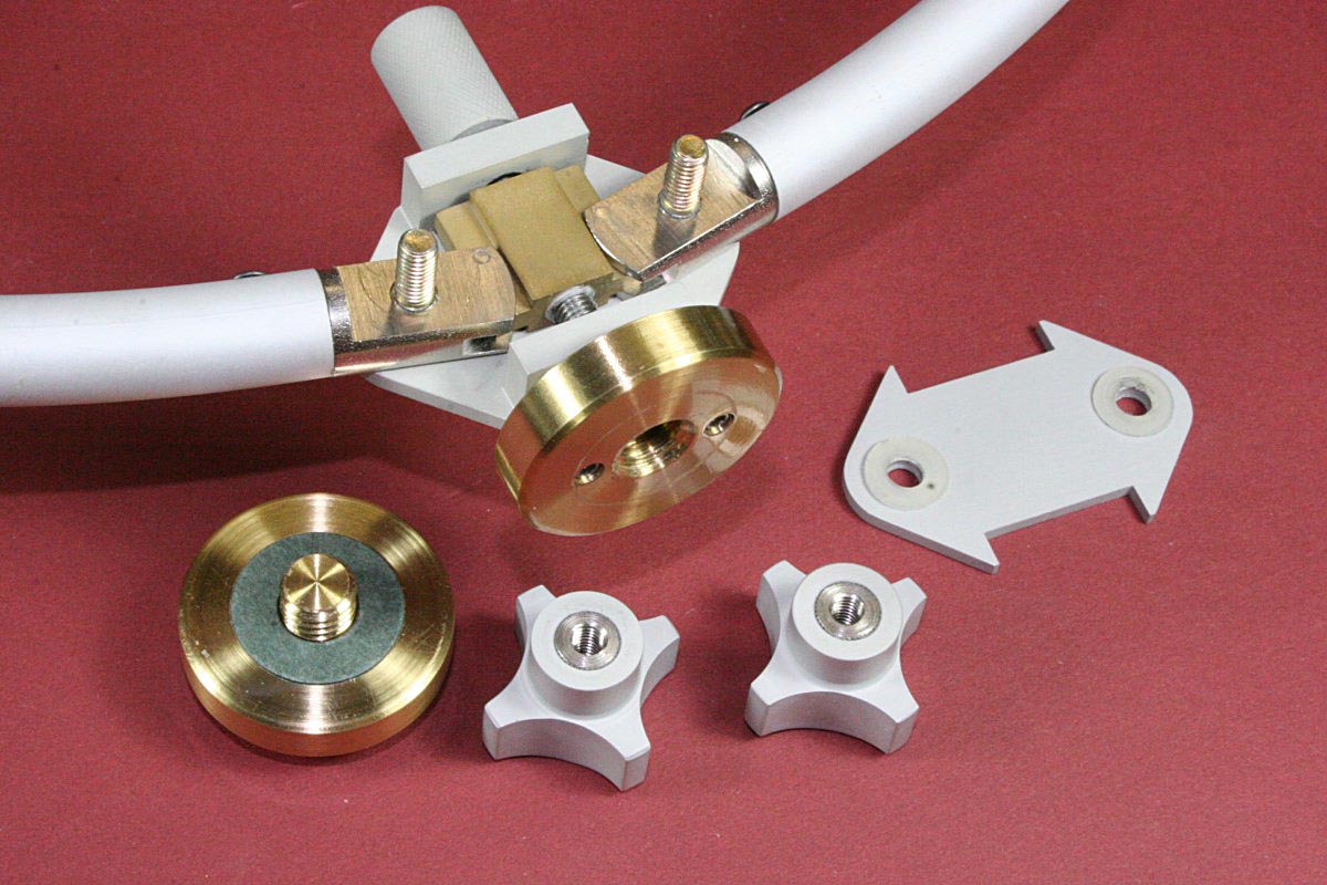
Anti-Roll Pendulum
This idea came to me while trying to figure out a way to have more stability in roll than in tilt. I rarely if ever want anything other than a perfectly level horizon in my video, but balancing the stabilizer to be bottom-heavy (with a fast drop time) meant that tilting up or down became a unwanted struggle. Ideally, I wanted a stabilizer that allowed free pans and tilts but one that would strongly self-level to be perfectly level in the roll axis. I don’t think I’m the first person to want this, but I couldn’t really search for examples of something that I could hardly describe. Anyway, this is my invention, even if its been done before…
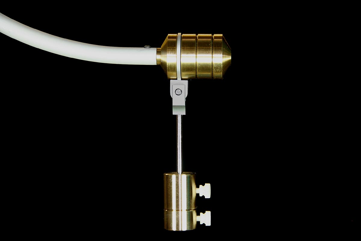
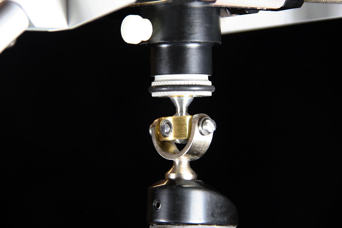
Roll Stabilizer Hangs Vertically for All Tilt Angles But Swings With the Boom for Rolls
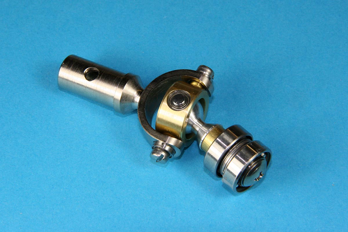
The Anti-Roll Pendulum (for lack of a better name) is a damped pendulum that is free to swing in the fore-aft direction but not sideways. The pendulum weights plus the mechanism replace an equal amount of boom counterweight. If the camera stabilizer is rolled sideways, the boom counterweights and the pendulum weights move together with the boom arm as a fixed group. The stabilizer is balanced so that the drop time from a roll is quite fast ( 1 second or even a bit less).
However, the benefit comes when the stabilizer is tilted up or down. The extra pendulum weights of a tilted stabilizer always hang straight down from the stabilizer’s pivot. For any tilt angles other than zero, the center of mass and the moment of the combined weights changes such that the tilt drop time can be very long compared to the roll drop time. Although the geometry is not perfect, it is entirely possible to obtain a nearly neutral tilt stability along with a very bottom-heavy roll stability for a very useful range of stabilizer angles.
Pendulum weight added to the stabilizer must be removed from the normal stack of boom counterweights. The location of the weights on the pendulum rod affects how much difference will be seen between the roll and tilt stabilities. Weights positioned near the pendulum pivot point will have minimal effect, but locating the weights at the bottom end of the pendulum arm will make the whole camera stabilizer heavy and self-leveling in roll and light (or even unstable) in up and down tilt. Of course each change in the pendulum weights requires rebalancing the stabilizer, but this is always performed by judging the drop time from a roll only and then observing the (longer) tilt drop time.
Decoupling the tilt and roll stabilities is useful for situations such as viewing elevated paintings on a high wall or looking up at buildings while walking, knowing that the camera is laterally level without having to work to keep it pointed upward (or downward).
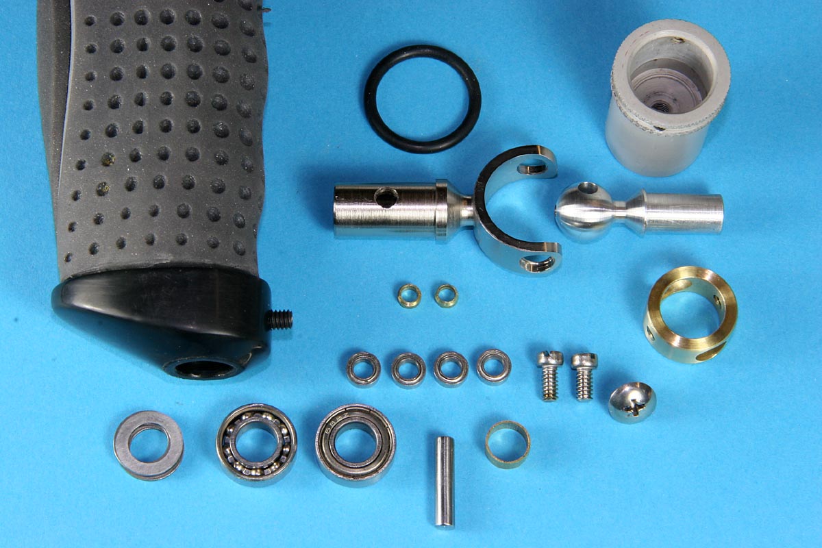
Despite its effectiveness and simplicity, there is one essential requirement of the assembly that is not obvious in the pictures. The pivot joint must be sufficiently free to allow the pendulum to easily hang straight down at all times, but this is NOT a place to use ball bearings. The bearing must have some surface area to allow the use of a viscous damping grease to inhibit any tendency for the pendulum to swing. The bearing used here has an internal bore of approximately .190″ and a length of .350″, and a grease was chosen that would allow the weight and shaft to drop from a 45 degree angle to vertical with no overshoot. Damping grease is commonly used on potentiometer shafts, microscope focusers, and binocular focusers and hinges.
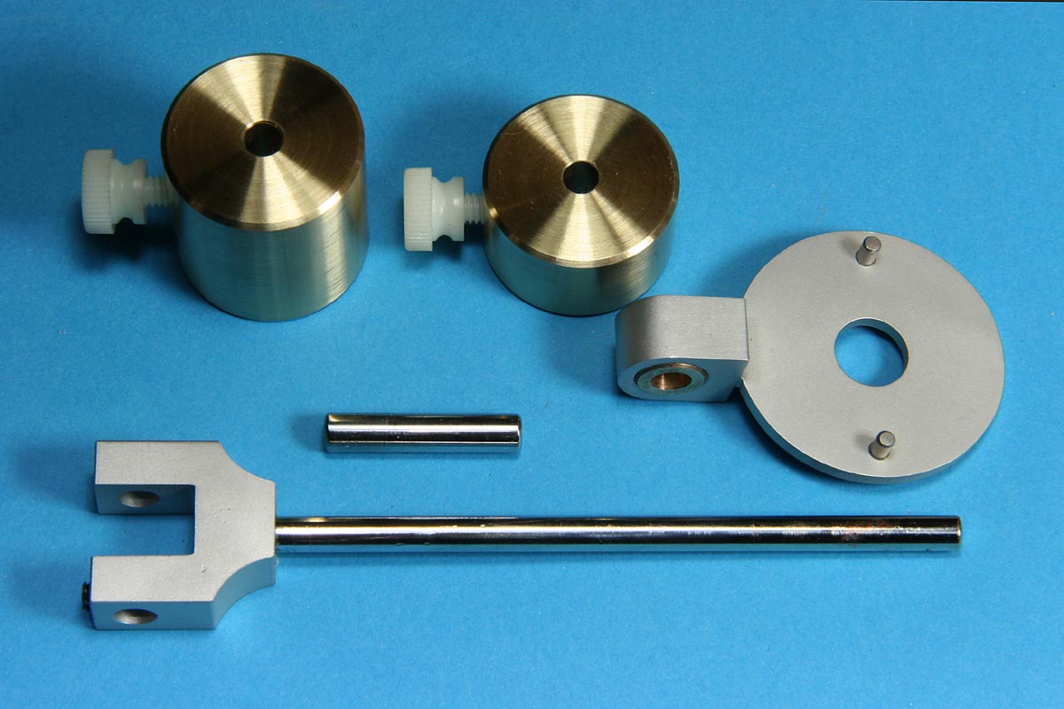
Parts for the Roll Stabilizer
Summary
This was a worthy machining project, and once balanced it works fine as a camera stabilizer, but it does seem needlessly complex both to build and to balance.
If I were to try this again I would consider using a similar camera platform with the x-y adjustments, but for the counterweight arm I would try using a modified vertical pole. I do like having the handgrip directly under the gimbal, so a possible design might look basically like this stabilizer but with a smaller, non-adjustable curve section (to give clearance around the handgrip) returning to a straight vertical section at the bottom. This would allow the use of a simpler, vertically sliding counterweight.
Stabilizer with my older Canon GL2
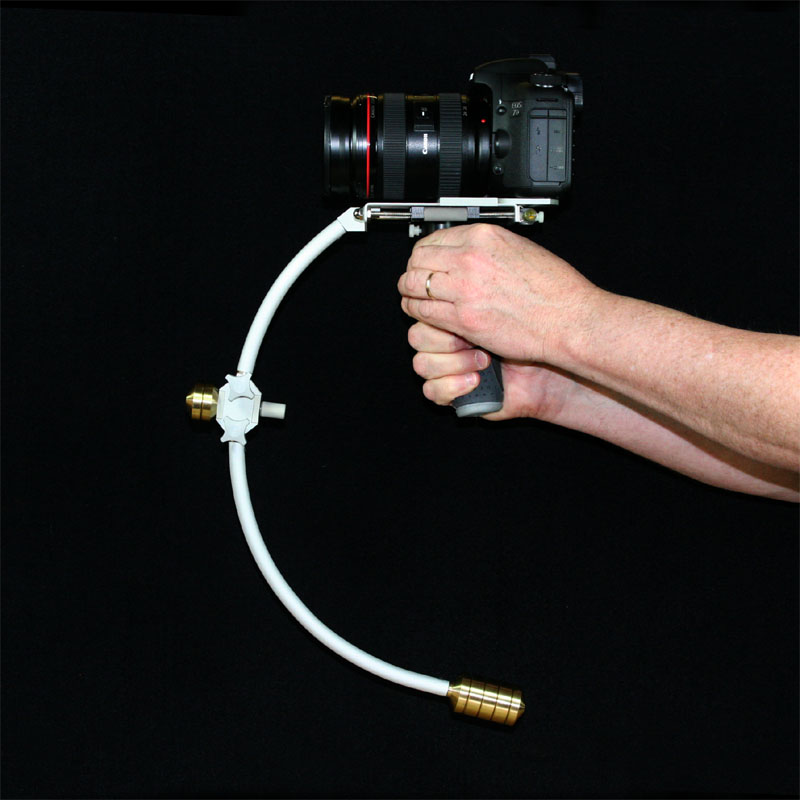
Canon 7D DSLR & f2.8 Lens – A Heavy Combo for Handheld Use
![]()