Pressure/Vacuum Casting Chamber with Camera
Allows Visual Monitoring of Degassing and Casting Operations
See What’s Going On Inside Under Pressure or Vacuum
Right or wrong, and subject to controversy, these are the general steps that can help produce bubble-free parts or molds using resin or silicone rubber:
- Measure out the two parts of the casting/molding material
- Mix any pigments or additives with one part of the resin or rubber, usually recommended by the manufacturer
- Optionally degas the components now – before combining – to minimize entrapped air or moisture. Do not over-pump below material’s vapor pressure, or you will create a nearly endless supply of new bubbles..
- Prepare to work quickly once the materials are mixed in the next step. The clock will be ticking…
- Thoroughly mix the two parts together, stirring and scraping the side walls. Transfer the mix to a new container if desired to minimize unmixed pockets of material.
- Fast-cure resins or mold rubbers may not give you time for this step, but degassing the mixture in a vacuum for a short time will help remove air entrapped in the stirring process.
- Remove the degassed mixture and carefully pour around part or into mold.
- Again, and only if time permits, quickly degas the the resin/mold or the mold-material/pattern to boil off bubbles introduced during the pour
- Apply 45 – 60 psi pressure to the casting chamber for the duration of the material’s cure time. This will minimize the size of any remaining bubbles in the resin or mold material. Note however that a soft rubber mold that is cured under pressure will generally always need to be used under the same pressure to cast parts; entrapped bubbles in a pressure-cured mold will bulge at normal atmospheric pressure and create dimples in the cast part.
Unfortunately, the following scenario has happened too many times in the rush beginning with step 5:
After mixing the casting resin for a part or silicone rubber for a mold, the mixing container is placed in a metal vacuum chamber for a quick degassing before pouring. A vacuum is pulled on the chamber to allow the major entrapped bubbles to boil off the material prior to pouring into a mold or around a part.
But then the vacuum chamber is opened, and lo and behold – the mixing container is nearly empty; most of the resin or mold rubber has boiled out of the cup and is puddled in the bottom of the chamber. It’s a mess, and it can be an expensive mess when wasting platinum-based silicones.
What Happened?
The problem with degassing in a blind vacuum chamber is that it is impossible to visually monitor and manually regulate the degree of vacuum to prevent the onset of violent boiling. A slow, overly cautious approach to blind degassing is usually not advisable when using resins that can snap cure in just a few minutes.
One solution is to buy or make one of the visible vacuum chamber designs that uses a thick-walled aluminum stock pot for the chamber and a thick clear polycarbonate (not acrylic!) plate and gasket for a cover. This provides a good size chamber with a wide and clear view of the condition of the mixture as it is being degassed. This setup cannot be used as a pressure chamber, however, because the plastic cover simply self-seals to the pot lip under vacuum – there is no latching mechanism. And after the degas-pour-degas sequence you would need to transfer the mold to a separate pressure chamber, assuming you have one. Except for the added transfer time, this is generally fine since there is little need to visually monitor pressure casting.
Although the concept of installing a sight glass in the lid of a pressure vessel such as a paint pot may seem handy and practical, a little thought about the engineering and fabrication of a safe design should be a deterrent unless you are willing to take the risks. The sight glass would have to be thick enough and mounted such that it can withstand a vacuum (not a big deal) and a pressure of 60psi (more of a deal but still manageable for a glass with small area). The complicating factor is how and where you deem it safe to penetrate the lid of the pressure chamber. Think of the area of lid (in2) multiplied times the rated 60psi (plus a safety margin) and you will understand the forces at work. Penetrating either a stamped or cast paint pot lid with a hole adequately large for a sight glass and mount is just someplace I did not want to go.
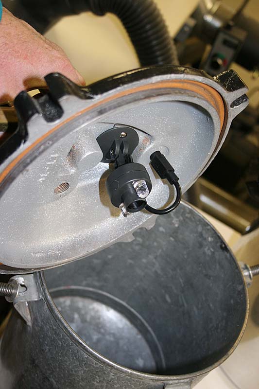
Add a Camera and Use a Single Chamber for Both Pressure and Vacuum
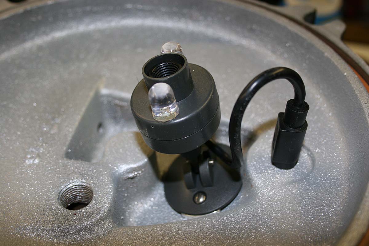
Closeup of the x10 Camera and the S-Video Plug
While this may seem to be a more complicated solution than necessary, very little fabrication effort was involved. I did need to have a video monitor or a computer nearby, and an outlet for power, but that was not a problem in my case. This has worked well enough that I plan to install a variation of it on a larger pressure chamber if I can find one. The pot shown here only has a 3 gallon capacity and more often than not is used on its side for the little extra mold space.
I made my test setup using an old x10 NTSC camera module that I had no use for. It was kept in its case with a tilt mount attached because it was small enough fit into a recess in the lid casting. The whole assembly does encroach into the working space a little more than an inch, but that has never been a problem. Very compact micro cameras are available from many sources, and it is a good idea to find one that can focus at close distances, even though focus is not terribly critical for the application. If a container of liquid is boiling over, you can generally tell what is happening whether it is finely focused or not. A USB camera could be adapted as well if you don’t mind having a computer nearby.
A standard-definition analog video camera generally requires only 3 or 4 wires:
- Analog Video Signal
- Signal Ground
- DC Positive
- DC Negative
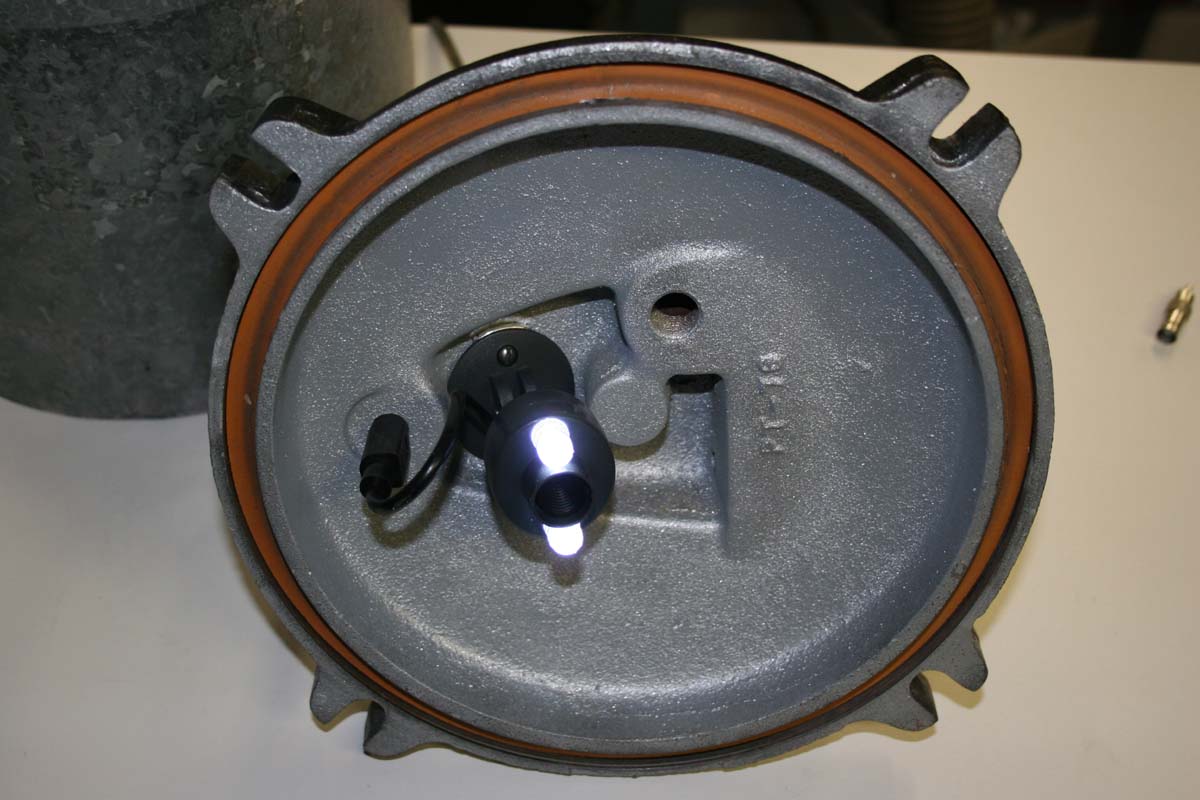
LED Headlights On
The camera is powered by an isolated wall-wart type of 12VDC power supply, so it is possible to share the Signal Ground and the DC Negative, resulting in only 3 wires for the gas-tight feed through. I added two white LEDs as a light source, sharing the 12VDC camera power. One or two 10mm LEDs are all that is needed; each LED should have its own current-limiting resistor in series to keep it operating under its maximum rated current. I used 1K? resistors for each of my LEDs running on 12V.
A reasonably gas-tight thru-cable fitting needs to be made to feed the camera signal and power through the pressure pot lid. This represents the only real fabrication work for a camera installation, and it’s not much of a project. It is basically made by potting the wires of the feed cable in epoxy where they pass through a gas-tight fitting or nipple. There are high vacuum epoxies available, but regular epoxy is just fine for this application.
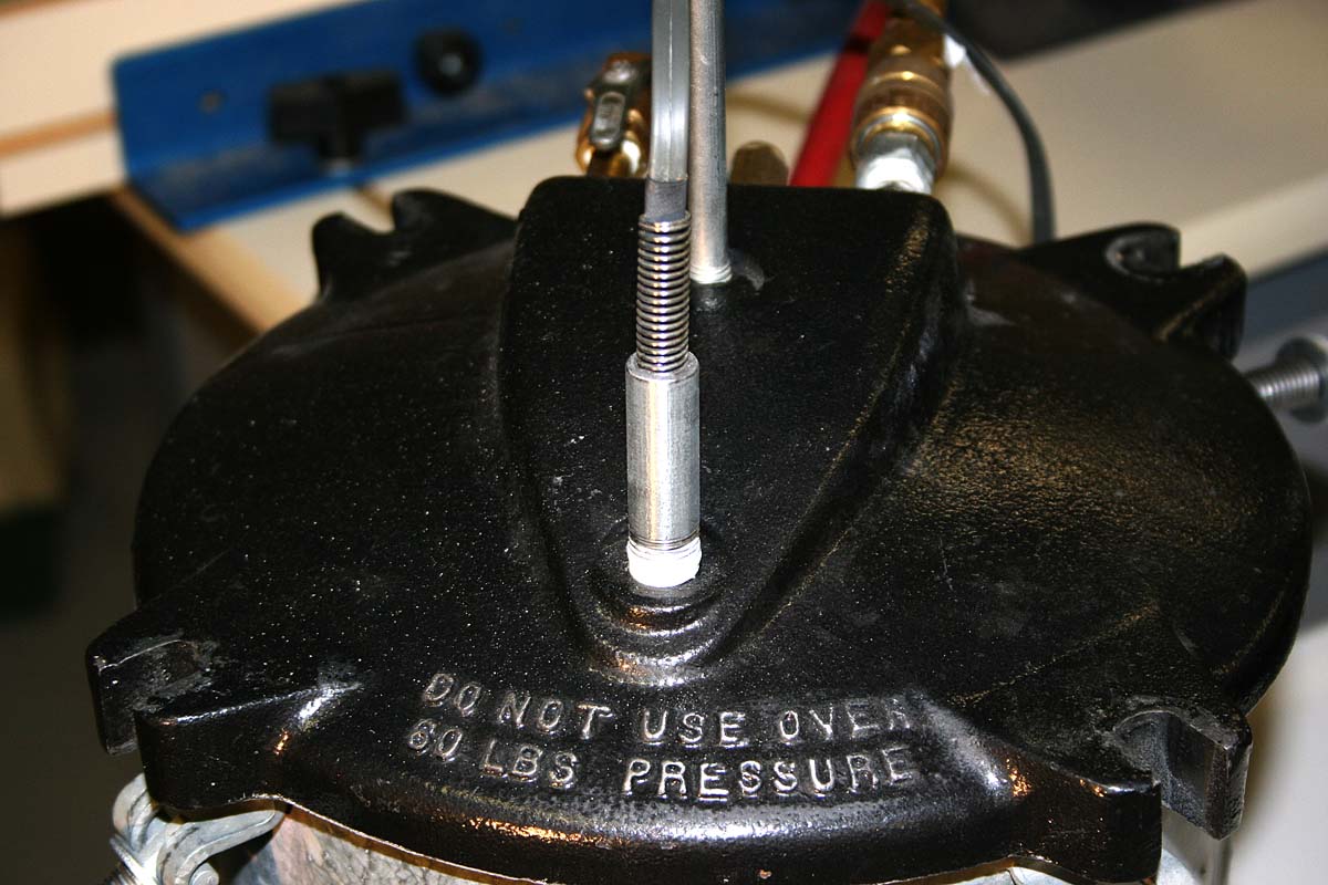
Pipe Nipple is Filled With Epoxy for Gas-Tight Cable Feed-Thru. Note Spring for Strain Relief.
My pressure pot has a cast iron top with a 3/8″ NPT threaded hole. For the feed-thru I used a section of 3/8 pipe nipple – this was large enough to fit an S-video connector (with rear solder lugs) into one end by boring it out a little. For a cable I use the flat 4 conductor lead that came with the camera. This cable is not critical; it does not need to be controlled impedance or even shielded for short runs. In fact, I had used this same camera a few years earlier to assist with the recovery of a broken well pump more than a 100 feet underground-over telephone wire!
For at least some of the length where the cable passes through the pipe nipple, it needs to be stripped of its outer insulating sheath. Otherwise this conduit can act as a pressure/vacuum leakage path through the potting material. The individual conductors could also have a short section of insulation stripped so that you get a copper-to-epoxy seal, but I did not find that necessary. If the camera cable that you use needs to be cut to be able to feed it through a small nipple (because molded ends are too large), the soldered splices can be conveniently buried completely in epoxy within the nipple. Stagger the splices a little and separate/insulate them to avoid shorting while the epoxy potting cures.
Feed the cable through the nipple, plug one end with clay, and pour an epoxy mix into the other end. Five minute epoxy is too fast to mix, pour, and have time to flow around the wires. Use something like a 4 or 24 hour cure time.
I grooved the inside of the pipe nipple slightly before pouring the epoxy so that there would be no danger of a cured epoxy bullet blowing out of the nipple under pressure.
This setup actually gets used more that I would have thought, and I am currently seeking a larger pressure chamber to allow casting of larger items.
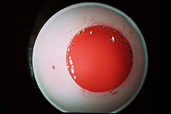
Camera View of Resin Bubbles on the Way Out.
It’s Not High Definition, But You Get the Idea
![]()