Blog Archives

Another D-Lev Digital Theremin Build Project

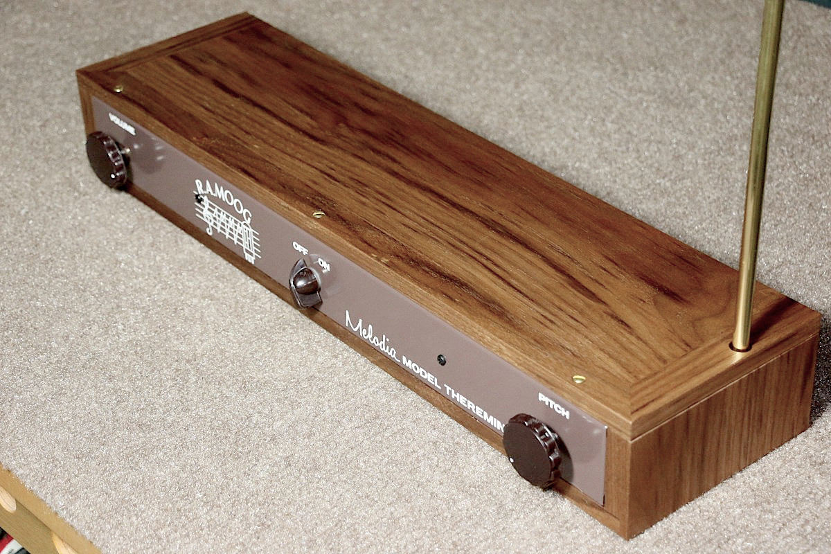
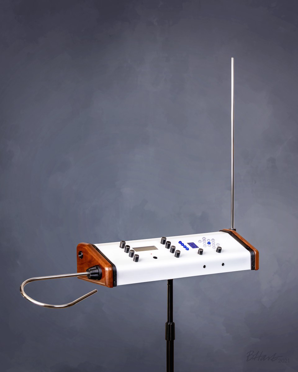
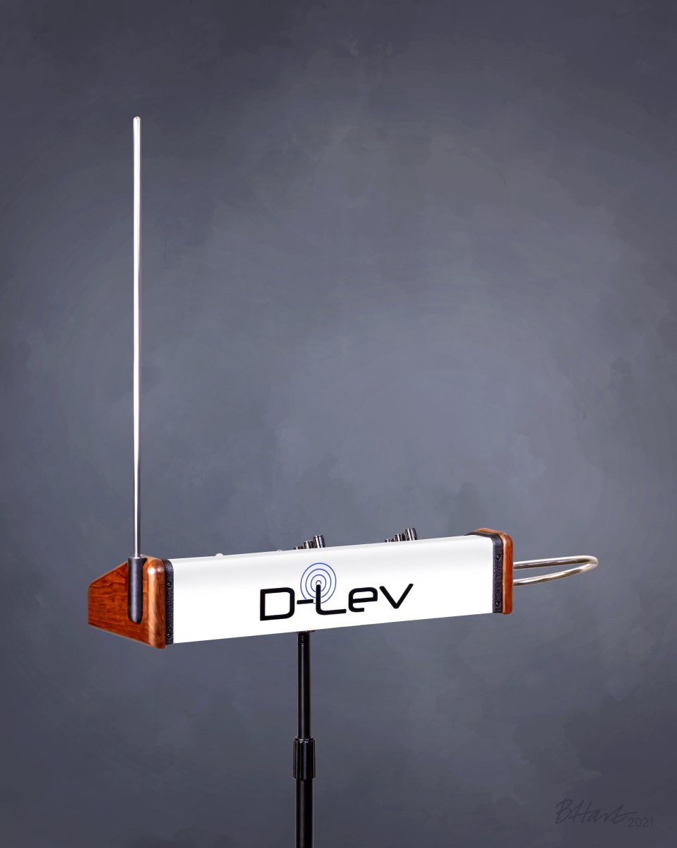
D-Lev Model P3, Serial Number 0002

This is my latest D-Lev prototype built for Eric Wallin.  It’s basically a white version of the first red one finished a few weeks ago.  I’ve tacked on a video demonstration at the end to prove that it works before I send it to him.


A long time ago I offered to build a finished theremin for Eric (Dewster) over at Theremin World (www.thereminworld.com) as a way of repaying him for sharing all of his secrets and letting me be the first early adopter of the D-Lev. At the time the idea was that his custom theremin would be the D-Lev “Tour” model which he had envisioned as road-worthy travel case with stowed antennas that would not just carry the theremin; it would be the theremin.  But too many undefined design issues and my thinly veiled lack of interest in making something like that led to the whole concept being back-burnered.
 
Finally a couple years later after coming up with a sort-of replicable design I decided to just build up an extra and give him a second model of my P3 enclosure and electronics, whether he wanted it or not, and consider it a promise fulfilled.
Read the rest


Building a Reproduction Moog Melodia Theremin

My completed reproduction of a 1960s-era Moog Melodia. Glamour shot by Becky Hart.

This model lacks the traditional volume loop antenna on the left side, instead using a plate of metal on the end of the cabinet (not visible here).

Why Build a Circa 1965 Theremin?

I don’t know why I became fascinated with the Moog Melodia enough to want to build a reproduction.  The physical appearance is very basic, and it has no timbre control, so you’re stuck with a single voice.  Part of the motivation for the project is that I enjoy doing restorations and have a great appreciation for the craftsmanship of antique and vintage items.  I also enjoy building from scratch, especially if the project has a nice mix of woodwork, metalwork, and electronics. With the Moog Melodia I get all of these.  I had no expectation going in that this was going to be a great theremin, but in the end it turned out to be better than expected, and it was fun to try to build something different.

I think the fact that the Melodia is well-documented helped to keep the scope of the project down to something that I was willing to do alongside other projects that are also competing for time.… Read the rest


A Homemade Progressive/Universal RF Coil Winder

The mostly-completed progressive/universal coil winder. The universal portion is my adaptation of Morris Coilmaster design with some added features. The progressive feature is new. All parts were designed in Fusion360 with the exception of the very nice 3-jaw chucks posted by user “mdkendall” on Thingiverse.com (link in text below).

A few years ago I became fascinated (obsessed) with theremins to the point that I’ve ignored maintenance of this website and I’m pretty sure I can’t even play guitar anymore.  The theremin is a miserably difficult instrument to play, but in the early morning hours when no one else can hear me I find a deep satisfaction in playing a musical instrument that almost seems to be connected directly to my brain.  If you can think of a melody you can play it (how well you can play it is another matter).

It’s strange that I resisted the theremin for so long in my younger years.  It is a natural fit in that it is an electronic instrument that uses radio frequencies and oscillators and filters, all stuff that I’ve been into since my pre-teen years.  The theremin story is for another time, though.  This project, a coil winder that allows one to make high-frequency coils with winding patterns that are impossible to do by hand, is actually a side task for a theremin construction project that I’ve managed to stretch out for over a year now. … Read the rest


Optoma HD20 DLP Projector – Dark Spot Repair

It Could Be Caused by a Burnt Lens That is Easily Fixable

Can You Find the Dark Spot Problem In This Image?

Can You Find the Dark Spot Problem In This Image?

Optoma HD20 DLP Projector

Optoma HD20 DLP Projector

The Optoma HD20 is a fairly popular DLP projector with a 1920 x 1080 native resolution and an attractive price tag. It also seems to be afflicted with an unusual tendency to suddenly develop a diffused dark area (sometimes inaccurately described as a blurry area) that may obscure part or nearly all of the projected image.  This sudden darkening may also be accompanied by a strong smell of melting plastic, because as in the case described here, plastic is actually melting and charring.

I had been looking for a full HD projector to use to build a high-resolution 3D printer, and I ran across this unit suffering from the dark spot problem on Craigslist for $100.  I was aware that projectors with this problem could be user-repairable, and when I looked at the unit I was able to see enough to determine that the large dark area on the right side was indeed caused by a melted inner lens.

Almost Unbelievable Meltdown of Internal Plastic Lens

Almost Unbelievable Meltdown of Internal Lens

The cause of the dark region on the projected image is an oddly-shaped aspherical plastic lens that is the final element in an optical path that channels light from the reflector lamp on the left front of the unit. … Read the rest

Tags: , , , , , , ,

A Milling Machine Spindle Camera

Modified Webcam Provides Tool’s-Eye View of Work


Camera Mounts in a 1/2" Collet In Milling Machine Spindle

Camera Mounts in a 1/2″ Collet In Milling Machine Spindle

It’s been a busy home-project summer (as in home-maintenance) but there have been a few shop projects that I have not had time to write about. One of these projects was the fabrication of a video camera that could be swapped for the milling cutter and used to precisely place a target under the cutter visually rather than by the numbers.

Sometime last spring I got the urge to buy and perform a CNC conversion on a small Grizzly G0704 milling machine.  Before beginning this project I knew there would be a need to machine stepper-motor adapters and other hardware components to a higher degree of precision and accuracy than I routinely care about.  And since many of the parts would have to mate with the machine castings, I needed a way to measure dimensions and hole spacings more accurately than by simply using a dial caliper.

Many other DIYers have built spindle cameras (I’m calling this one a mill-cam from here on), and a web search turned up several different approaches.  I incorporated many of their ideas into this design and added a few of my own, including the ability to adjust the tilt the vertical axis of the camera.… Read the rest


DIY Resistance Soldering Outfit

Put Soldering Heat Where You Need it – Now!

This Home Resistance Soldering Rig Can Deliver Over 350 Watts of Pinpoint Power

This Homemade Resistance Soldering Rig Can Deliver Over 320 Watts of Pinpoint Soldering Power

Resistance Soldering

Resistance soldering is a process by which objects to be soldered together are heated by passing a current through them rather than by applying heat from an external source. Localized heating is caused by relatively high current passing through the resistance of the junction. As long as the heating rate of the junction exceeds the thermal dissipation rate, the temperature will rise high enough for solder to melt and flow.

There can be several advantages to using resistance soldering for certain applications, but two big ones stand out:

  • Speed – a resistance soldering unit can generate heat in a localized spot much more quickly than application of a 700 to 800 degree soldering iron which relies on conduction for heat transfer. A resistance soldering unit can also exceed soldering temperatures, heating a junction to bright orange, actually welding small parts together.
  • Steep temperature gradient – because of the rapid heating of the joint being soldered, it is possible to obtain a very high temperature gradient over a short physical distance, making it easier to prevent nearby solder joints from melting and falling apart.
Read the rest
Tags: , ,

Edge-Lit TVs Are Like a Box of Chocolates…

Displaying LCD Technology in the Worst Possible Light

composite_LR

Top Left – Clouding
Top Right – Dirty Screen Effect

I would guess that LCD TV enthusiasts, owners, and potential buyers that lean more toward the videophile/home-theater end of the spectrum represent a fairly small percentage of the overall market. If you are part of this minority and follow discussions on AV forums dedicated to such topics, you will learn about quality control issues that plague just about every make and model of flat-panel TV on the market. In some cases you will learn about flaws that you may never have noticed on your own, and once they are seen they usually can’t be unseen. But it is better to be able to spot a problem immediately within a return or warranty period than to suddenly discover it on your own when it is too late. Being informed can assist you in making a better choice in selecting a TV; it can also cause frustration to find out that no matter what make or model you choose, luck almost always plays a role.

It is pure speculation on my part, but it seems plausible that the Edge-Backlit LCD TV business model has settled on this general quality control philosophy:

If it lights up and displays a picture, ship it.Read the rest

Tags: , ,

A $20 Transistor – L/R/C ESR Tester

Displays Device Parameters and Lead Configuration

IMG_7811_LR

Displays Battery Voltage While Testing (or Looking For the Nonexistent DUT)

I don’t know how long these have been available, but they are pretty cool. These testers are all over eBay in various forms for around this price, give or take. After ordering this I found a different one for about $23 with a built-in ZIF socket, which would have been handy instead of the pin socket shown here. But that didn’t have the ultracool white-on-blue backlit display.

Display Unplugs From Processor Board

Display Unplugs From Processor Board. The Trimpot Adjusts the Display Contrast.

I am really surprised how well it works. It runs on a 9v battery. There are three available connection points (pins 1-2 are connected, as are pins 4-5 on the socket) marked T1, T2 and T3. For 2-terminal devices use any two connections, and for transistors use all three. You do not need to know diode or transistor lead configurations for the test – it finds them for you. SMD pads are available on the main board itself for testing surface mount components.

When a device is connected and the test button pressed, the display initially shows the battery voltage. After a short time the display will show a symbol of the component and the assignment of the pin numbers in accordance with the way you have the part connected.… Read the rest

Tags:

Equalizing CRT Phosphor Wear Patterns

Re-Use or Extend the Useful Life of CRT Projector Tubes

Proj A_green tube mod 533

Phosphor Wear Pattern on Face of One of Two Green CRT Projector Tubes.
The Effect of This Wear Was Reduced Using the Procedure Outlined Here

Note: this article is several years old but may still be of interest to some home theater enthusiasts.

CRT (cathode ray tube) projectors may be a dying technology, but they are not dead yet. Despite their size and weight compared with digital projectors, CRT projectors have some advantages that an enthusiastic subculture of home-theater aficionados cannot abandon, at least until something truly better comes along. CRTs can produce the deepest and most uniform black levels, and tube life far exceeds the lamp life of a digital. CRT projectors, despite their complexity, are highly repairable compared to a typical digital projector where even the replacement of the lamp may be cause to abandon the whole unit and buy another.

In a CRT projector three separate images produced on the faces of red, green, and blue tubes are converged and projected via separate lenses onto a screen to create a full color image. The light is actually produced by an electron beam striking a phosphor coating on the faces of the tubes.… Read the rest

Tags: , , , ,